TCD1304-based spectrometer - Part 2
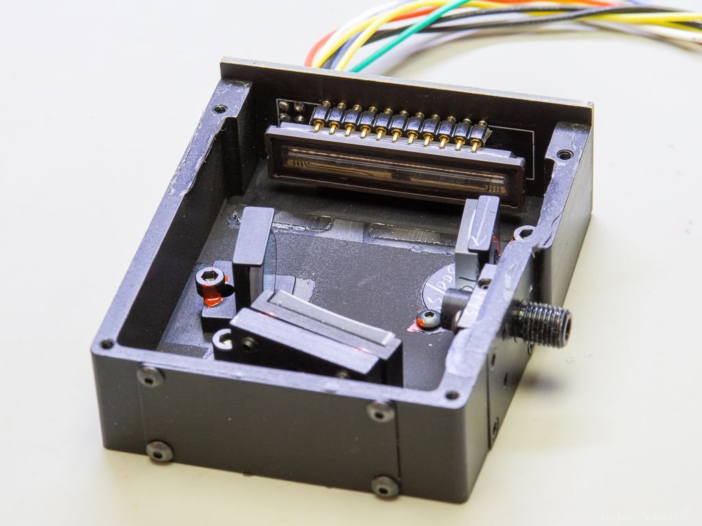
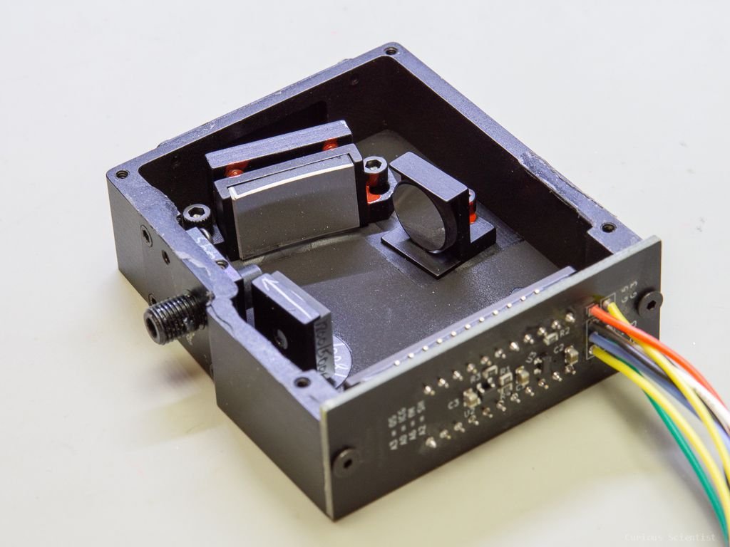
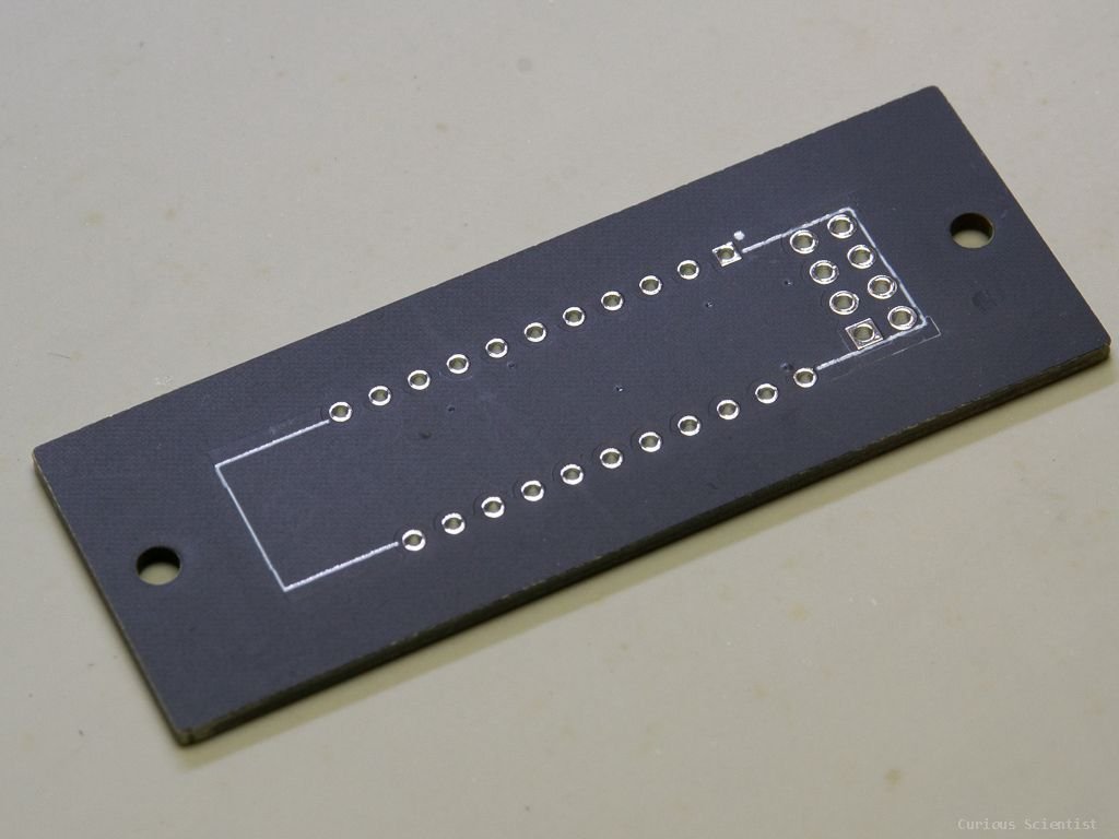
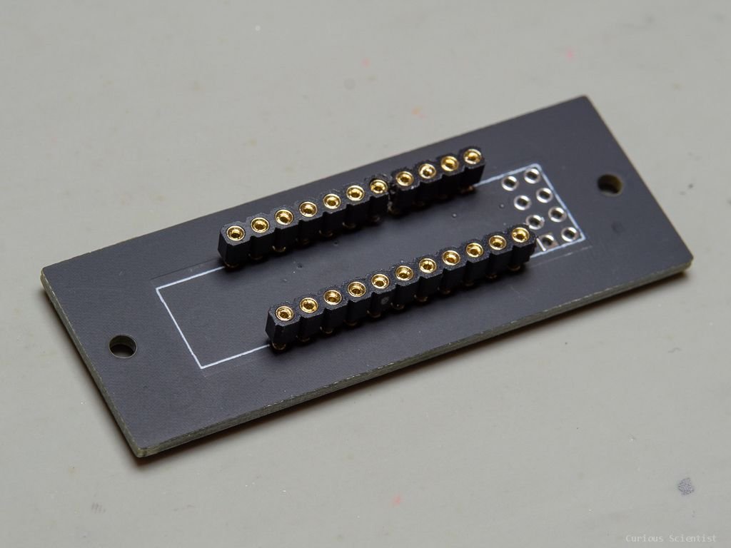
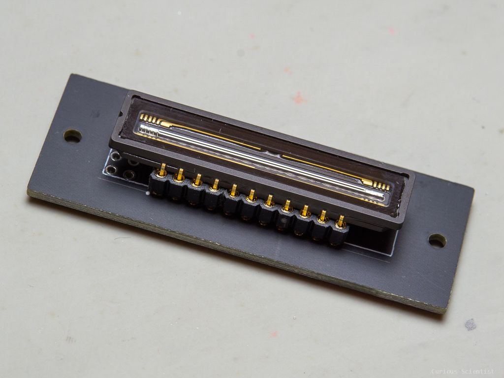
In this video I continue my journey with my DIY spectrometer. I received my new PCB that I designed to fit the enclosure of the optical bench (B&W TEK BRC100 OEM). Obviously, I made a little measurement mistake so the mounting holes were a bit off, but I was able to fix it with a grinding tool without negatively affecting the PCB in any sense. The reaming of the holes is unnoticeable because the head of the mounting screws cover the expanded holes anyway.
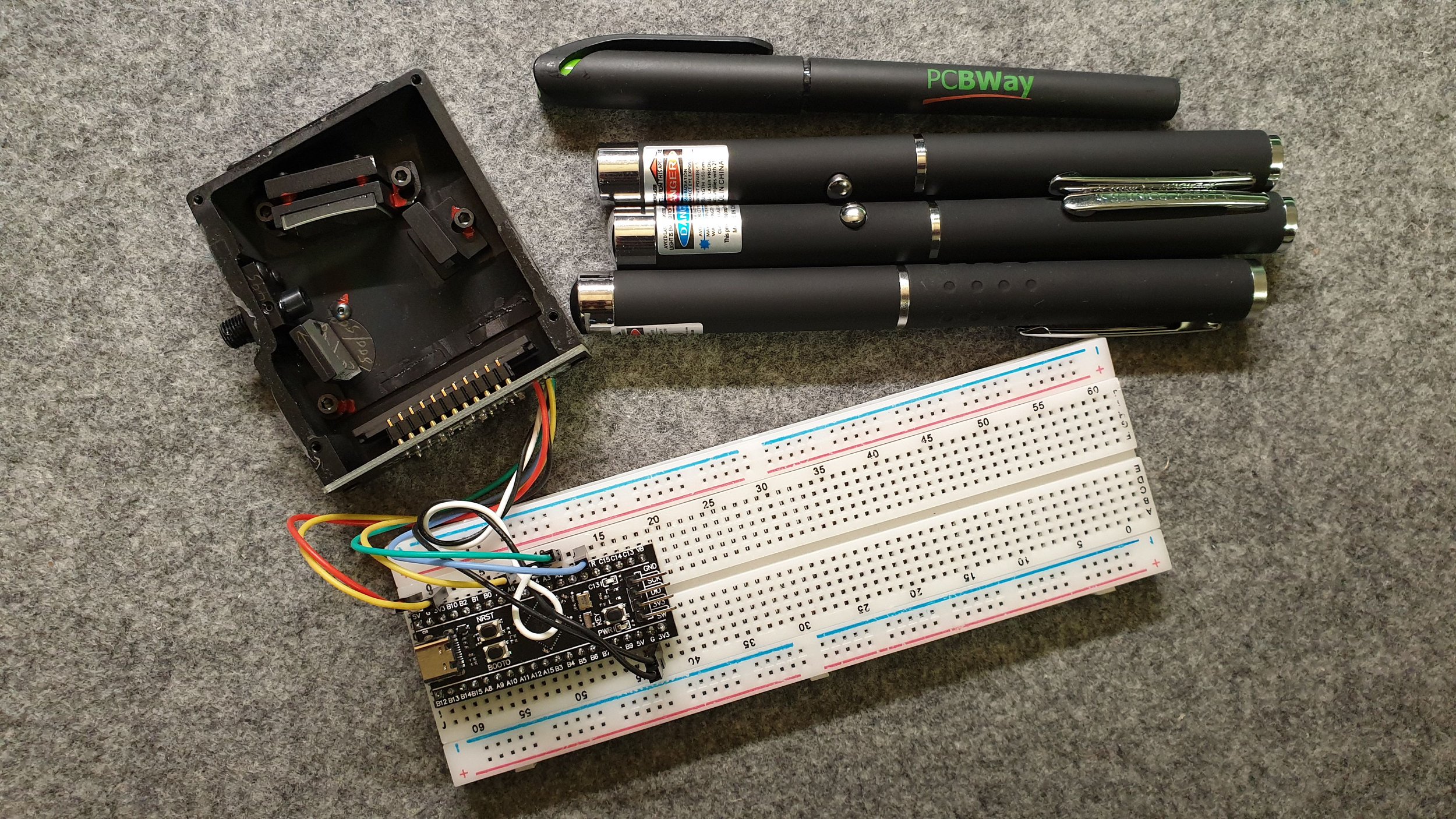
Anyway, the circuit works perfectly and it was not at all noisy despite the fact that I expected some noise because I used relatively long wires to transfer the signal between the microcontroller and the CCD. I have another circuit assembled on a breadboard and the signals are really bad as compared to the signals I can measure on the PCB.
I also showcase my updated software for receiving and processing the data coming from the linear CCD via the microcontroller. The software can plot the output of the CCD in real-time, it can save the data into a file and can do averaging. I also properly implemented a way to change the integration time for the CCD from the computer.
Extra pictures and resources

Join my YouTube membership!
Buy my PCB using the link below:
