Improving my reflow hot plate
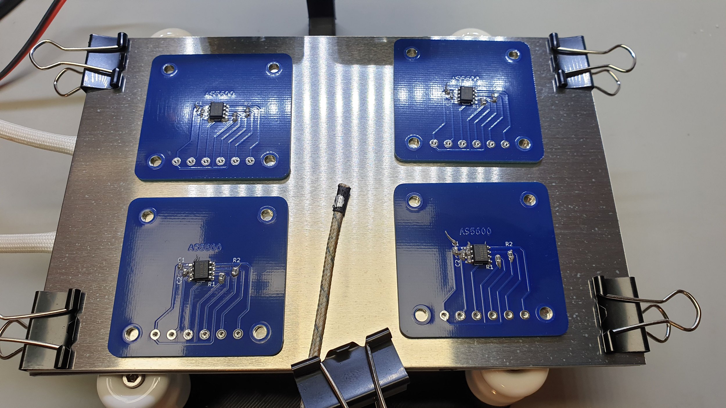
In this video I am going to show you my latest improvement regarding my DIY reflow hot plate. In the previous videos (1 and 2) I showed you how I constructed and used the soldering station, but I was never 100% satisfied with it. I am quite satisfied with the electronics part, but in the beginning I had issues with the ceramic heating plate I used. Due to its structure it was not heating the PCBs homogeneously enough which lead to inhomogeneous soldering. While one part of the board was already hot enough to melt the solder, the other side of it was still too cold and the solder paste was solid.
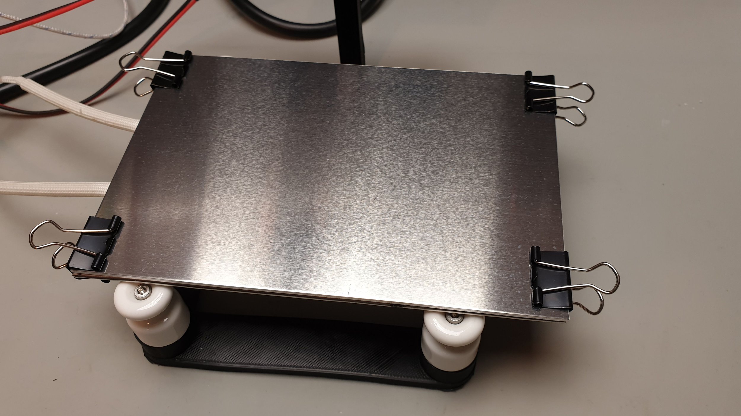
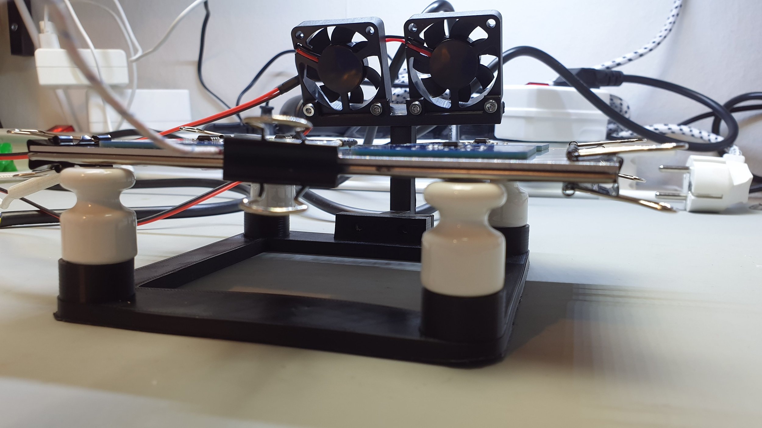
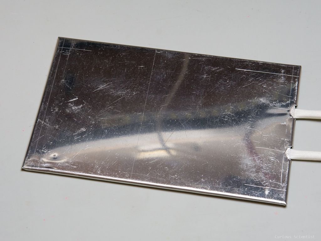
This video tackles the issue. I replaced the ceramic heating element with a mica heater and in addition, I attached a 1.5 mm aluminium plate to the mica plate. Unfortunaltely, the mica heater is not perfect either. It has a really good thermal response as well as it can heat up really fast, so it can follow the heating curve well. However, during heating the heater becomes swollen like a pillow which means that its surface will not mate the bottom of the PCB perfectly anymore. This will also lead to inhomogeneous heating.
My solution for the above described issue is to attach a 1.5 mm thick aluminium plate to the mica heater. This leads to multiple improvements. First of all, the main improvement is that the whole heating surface gains additional rigidity and it will not become curved during heating. Furthermore, the addition of the thin aluminium sheet helps to “homogenize” the temperature distribution across the surface as well as it helps to smoothen the heating because of the added “thermal inertia”. The heat will need a bit more time to reach the PCB because first it has to be transferred from the mica heater through the aluminium sheet.
Additional images and resources
Useful affiliate links for the parts I used in this project:
Buy my PCB design from PCBWay

Join my YouTube membership!