How not to fry your Arduino?
In this video, I will try to show you the most common mistakes that people make before they fry their Arduino. There are multiple fundamental issues that beginners overlook which causes them to destroy the microcontroller. Actually, most of these issues could be simply solved by reading the datasheet of the microcontroller, but quite many people don’t bother to do it. So, I do it for those people and try to help by giving well-detailed examples of how to avoid such mistakes.
How do you even fry an Arduino?
Alright, so let’s start with the basics. What do I mean by frying the Arduino? I simply mean that the user tries to run a more-than-possible current through it which will cause one (or more) of the components to give up.
There are multiple ways to destroy an Arduino. To understand what makes it fail, let’s first study its power management. In my examples, I will study an Arduino Uno, because this is one of the most common beginner microcontrollers. Some concepts as you will see can be transferred to other boards too, but there are also some Arduino Uno-specific things. So, after learning everything from this article, always refer to the datasheet of your specific microcontroller of choice.
Power management
An Arduino Uno can be powered in multiple ways. The most straightforward way is to connect a USB cable to it. Another way is to connect a 7-12 V power supply to its DC jack. These are the most common standard ways. But one can also connect an external 7-12 V power supply directly to its VIN pin. This has nearly the same routing as the VIN pin, except that the DC jack has an extra diode in series. So, directly connecting a power source to the VIN pin will still go to the onboard 5 V voltage regulator, however, it won’t be protected against reverse polarity. Even more adventurous users can connect an already regulated, stable 5 V power supply to its 5 V pin, but in this case, the onboard 5 V regulator is bypassed, so the users must know what they’re doing. The Arduino Uno should not be plugged into the USB if an external power source on its +5 V rail is present (+5 V powered directly)!
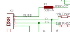
F1 fuse on the 5 V from USB
So, this is all about the voltages, now let’s see the current. I use the Arduino Uno Reference Design schematics in this analysis.
First, let’s look at the 5 V rail coming from the USB. Right after the USB connector, there is a 500 mA fuse (F1). End of the story. Even if you could supply more than 500 mA via the USB (certain chargers allow 1500 mA or USB 3.0 allows 900 mA), you could not draw more than 500 mA without blowing the fuse. Since the Uno draws around 50 mA by itself, you are left with 450 mA available in the whole system. We return to this value soon.
So, when powering the Arduino via the USB, the max possible current consumption is 500 mA, minus 50 mA which is drawn by the microcontroller itself.

5 V LDO (MC33269D-5.0) on the DC jack and VIN power rails
Then, there’s another way to power the Arduino which is via the DC jack or the VIN pin. They both end up at the same place, at the input of the onboard voltage regulator (MC33269D-5.0), so it does not matter which pin is used. Just don’t connect a power supply to both the VIN and the DC jack! Using the onboard voltage regulator, there will be a little more current available on the 5 V rail because the regulator is an 800 mA regulator. Of course, the power supply connected to the DC jack should be able to source this 800 mA. So, ideally, 800 mA - 50 mA = 750 mA is the available current on the 5 V rail when the VIN or the DC jack is used. Still, there are a few things to keep in mind.
First, the external power supply should be able to supply enough current. Ideally, a 12 V, 1000 mA power supply would be a good choice. But for example, a 9 V, 500 mA power supply would be sufficient as well if you are not planning to connect too many things on the 5 V rail. Both of these power supplies have their advantages. This leads us to the next good-to-keep-in-mind thing. The onboard voltage regulator is an LDO (Low Drop Out) voltage regulator. The way they work is simple: To provide a stable output voltage they dissipate the voltage difference between the input voltage and the output voltage as heat. This means that if you have a 12 V power supply and the output voltage of the LDO is 5 V, the LDO has to dissipate 12 V - 5 V = 7 V, times the output current of the LDO. When this configuration is running at let’s say 500 mA, that is 7 V * 500 mA = 3.5 W. That’s quite some heat (power dissipation)! However, when you use a 9 V power supply, the voltage difference becomes 4 V. If we still consume 500 mA, the power dissipation becomes 2 W. Almost half of the previous amount!
This is why Arduino recommends a maximum of 12 V as the input voltage through the VIN pin or the DC jack. Even though the LDO could accept 20 V as its input voltage, the power dissipation would be way too high and it could lead to damaging the circuit. At 20 V input voltage, the drop would be 15 V. At 500 mA current, the power dissipation would be 7.5 W. That is probably way too much heat.
So, how does the Arduino manage these power sources? Let’s look at the schematics again, because there are some cool tricks there.
Let’s start with the USB. When we connect a USB cable to the Arduino, then the power is also supplied by the USB cable. If it is connected to your computer, then most probably it can receive up to 500 mA. This 500 mA is the limitation of the USB 2.0 standard, but as I mentioned above, the 500 mA fuse would also restrict the power to 500 mA. Then the circuit continues after the fuse and it goes into the drain of a P-channel MOSFET (FDN304V). Due to the working principles of the MOSFET, this 5 V can pass through the MOSFET and eventually turn it on which finally allows the VUSB to “become” the onboard 5 V. From this point, this 5 V powers everything. This is the global +5 V rail across the whole board.
An alternative way to power the board is to use the VIN or DC jack. Since these inputs are made for larger than 7 V voltages, whatever voltage enters them first must go through a voltage regulator. Then after the voltage regulator, the +5 V rail is fed with power.
However, if you have read carefully, you might ask what happens when both the USB and the VIN/DC jack are plugged in. Wouldn’t there be a conflict?

Arduino Uno’s MOSFET circuit
Well, yes, there would be, but thanks to the onboard MOSFET, there will be no issues. So let’s go back to the MOSFET and understand how it works and why it is in the circuit.
Let’s unplug everything in this thought experiment and plug in the USB first. 5 V comes in, crosses the fuse, and then reaches the drain of the MOSFET. As I wrote above, the 5 V from the USB has no problem reaching the +5 V rail on the Arduino. So it somehow makes it through the MOSFET. The following conditions allow this. If we zoom out a bit, we see that the gate pin of the MOSFET is connected to the output of an LM358D OP-AMP. The inverting input (-) of the OP-AMP is connected to the 3.3 V supply and the non-inverting input (+) is connected to the output of a 1:1 voltage divider whose input voltage is the VIN rail, so the voltage from an external (non-USB) power source. If there’s no VIN, or more precisely, if the VIN is below 6.6 V, the output of the OP-AMP is zero.
Side note: this also explains why the minimum recommended VIN is 7 V. The 5 V LDO would work at 6 V already (it has 1 V dropout) but at 6 V VIN, the OP-AMP would still not turn on its output pin. Also, at exactly 6.6 V, fluctuations might mess with the OP-AMP which might lead to oscillations and the MOSFET would go bananas. So 7 V is a good enough overshoot to make the OP-AMP stable and keep its output on.
To understand what this zero voltage on the OP-AMP’s output does to the MOSFET, let me talk about the MOSFET first. So, in this default state when the gate is at 0 V, the following happens. The 5 V reaches the drain and then it “drops” through the body diode of the MOSFET. So let’s say around 4.2 V reaches the source. Now, to make a P-channel MOSFET conduct, the VGS value should be smaller than its gate threshold value. This specific MOSFET has a VGS threshold between -0.4 V to -1.5 V. The VGS is determined by subtracting the voltage of the source pin (VS = 4.2 V) from the voltage of the gate pin (VG = 0 V). This gives us VGS = -4.2 V which is more negative than -1.5 V. This will enable the MOSFET to conduct between the drain and source pins, essentially “knocking out” the voltage drop caused by the body diode as well.
Then when the VIN is also connected and the voltage is above 6.6 V (remember, 7 V is the minimum recommended), the OP-AMP outputs 5 V to the gate pin of the MOSFET. In this case, VGS = 5 V - 5 V = 0 V which is more positive than the -0.4 V (largest absolute threshold voltage). This immediately shuts the MOSFET off. In this case, the global +5 V rail is powered by the onboard regulator fed from VIN. Since the MOSFET is off, the 5 V from the USB and the 5 V from the regulator are not in contact. This essentially allows us to power the Arduino Uno while it is still connected to the computer. Thus, we can still communicate with it while running something more power-hungry projects.
Examples and solutions
I want to show you some typical mistakes that people make when they fry their Arduino. They are typically related to motors. Motors, even the small ones can draw high enough current to permanently damage the Arduino.
One of the most typical examples is when the user tries to use the SG90 servo motor in a project.
First, let’s understand the servo. This is a 3-pin device: it has a power pin (+), a ground pin(-) and a signal pin (PWM). According to the specifications, the supply voltage should be between 4.8 and 6 V. The maximum current draw of the motor at 4.8 V is 500 mA. I guess now you see where this is going.
The problem is that many new users try to connect the power pin of the servo directly to the 5 V pin of the Arduino. As I said earlier, the available current on the 5 V pin in the ideal case is a maximum of 450 mA (500 mA from the USB, minus the 50 mA consumed by the Arduino itself). When the motor tries to draw 500 mA, and on top of this the Arduino draws 50 mA, the total current the the system tries to draw now is at least 550 mA. If the USB can supply more than 500 mA (USB 3.0 or battery charger), then the circuit will be able to draw it initially, however, the fuse on the board would trip and cut the circuit. In lucky situations, the fuse would recover if the user is fast enough to remove the power, otherwise, the fuse could burn. In this case, the fuse must be replaced.
To fix this, the motor should be driven from an external power supply. In the image below, I created a circuit which would be ideal to run both the Arduino from a 1000 mA 5 V power supply. 1000 mA would allow to run the motor at its maximum rated current while still having 500 mA for the whole Arduino as well.
Important!
If the Arduino Uno is connected to the USB, the 5 V connection between the external power supply and the Arduino Uno should be removed!

Wrong and correct* connection of a servo motor.
*Assuming that the user does not power the Arduino by any other power supply, including USB!
The following remarks should be considered:
If the external power supply is a stable 5 V power supply, it can be used to directly power the 5 V rail of the Arduino. Only do this, if the power supply is trustworthy because this method circumvents the onboard 5 V LDO!
Furthermore, do not use both an external 5 V power supply on the 5 V pin and the USB connection. If you want to use the USB, do not connect the 5 V pin to an external power supply!
When using an external power supply, make sure that the ground connections are shared across all the components. The ground from the power supply should go both to the motor and to the Arduino.
If the ground of the power supply is only connected to the motor, then there is no return path for the servo signal and there is no return path for the 5 V either. Basically, they are open circuits.
If the Arduino is powered by the USB or by VIN, the 5 V wire between the power supply of the motor should be removed. The ground pin should still stay!
Note: Even if you would power the Arduino via an external power supply, it is still not recommended to use the 5 V rail on the Arduino to power the motor. When using VIN, the available current on the 5 V rail becomes 800 mA and this 800 mA would not pass the fuse as in the case of the USB connection. However, it is just simply good practice to not connect any power-demanding stuff to the “delicate” microcontroller.
Another, also motor-related issue is with DC motors.
First, the biggest no-no is when the user tries to switch the motor directly with a GPIO pin. Let’s say, one of the connections would go to pin 4 (positive) and the other would go to GND.
In this case, when the user writes digitalWrite(4, HIGH), pin 4 would go HIGH (5 V) and it would allow the motor to draw current. The problem is that the GPIO pin can only supply up to 20 mA, and also the total current (combined) through all the GPIO pins should not exceed 100 mA. So trying to drive a motor that could take up let’s say 750 mA would violate both rules and would either fry the Arduino or it would just not work.
For example, the DC motor I tried in the video draws roughly 68 mA at 5 V, however, it needs a much higher current when I start it. The motor does not start when the power supply is limited to 100 mA. So both the initial >100 mA current draw and the steady-state 68 mA at 5 V would damage the Arduino’s GPIO pin!
Then let’s say, in the next step the user realizes that motors can be switched with a relay or a MOSFET. But they still make the mistake when they try to connect the power pin of the motor to the 5 V rail of the Arduino. If the Arduino is powered by USB, then the onboard fuse will be blown. If the Arduino is powered by VIN, then there’s a chance that the motor will run, but there’s a chance that the LDO sooner or later overheat and give up. Also, when using a relay or MOSFET to switch a motor, people often forget about the flyback diode. But this will be another article’s topic.
The solution is almost the same as for the servo motor. We need to use an external power supply, and also a dedicated motor driver. In the example below I show a motor driver example. The TB6612 is a relatively modern one. Some people still use the L298N due to its price and availability, but it is not recommended.

Wrong and correct connection of a DC motor.
Summary
Follow these rules to avoid frying your Arduino.
Create a power budget
Assuming that the Arduino is powered by USB, the board can provide about 450 mA on its 5 V rail before blowing the fuse
Look up all the loads’ (displays, LEDs, sensors, modules…etc.) current consumption on Google (use their datasheet or specifications) and sum up the total current draw. Do not exceed 450 mA, or even 400 mA in total!
If your loads would consume more than 400 mA, consider using an external power supply. A 5 V 1000 mA power adapter is typically a good choice.
Do not power anything from GPIO pins. GPIO pins are only for signals, they are not power sources (or sinks)! They can not provide more than 20 mA per pin and in total, they can not provide more than 200 mA.
For example, when using pull-up resistors for a switch we use 10k resistors to limit the current
When lighting up LEDs with GPIO pins, we should respect the 20 mA rule! Do not use any resistor below 250 Ohm (5 V / 250 Ohm = 20 mA) as the current limiting resistor. I did not consider the voltage drop to add a safety margin! If you really want to max out the possibilities, let’s say the forward voltage of the LED is 1.6 V. In that case, the formula becomes 3.4 V / 170 Ohm = 20 mA.
Use dedicated driving circuits for DC motors. This does not only protect your Arduino but it adds the possibility of speed control and direction control.
Do not try to directly drive a DC motor from an Arduino, especially not by using the GPIO pins.
Consider using a flyback diode when switching the motor with a MOSFET or relay
Do not forget about the ground connection
People often forget to connect the ground of the Arduino to the driven circuit when the circuit is powered by an external power supply. This could lead to erratic behaviour.
Always double-check the polarity of the power supply
Some power adapters have central positive connectors, while others have central negative connectors. Use a multimeter to determine the polarity!