Custom DRO PCB, but for rotary encoders
In one of my previous projects, I introduced my custom-made PCB which takes the output signal of a DRO and converts it into a human readable value which is then shown on a OLED display. The soul of the system was an ATtiny85 microcontroller. I also added a button to the circuit which functions as a tare button.
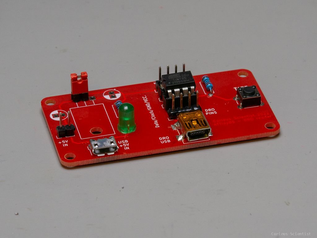
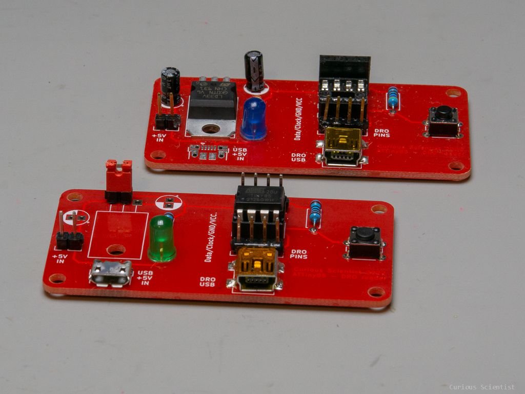
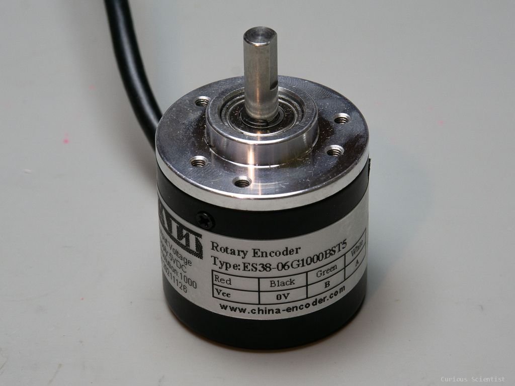
In this project, I show you that this circuit can also read and process the output signal of rotary encoders. First of all, since these rotary encoders I use operate at 5 V, we can get rid of the voltage regulator part of the circuit. Basically, we can remove the voltage regulator and its two capacitors, and short out the first and second pin of the regulator (I used a jumper pin in the video). Then, we just need to reprogram the microcontroller a little bit and use one of the pins as an interrupt pin to properly catch the pulses of the encoder.
If you would like to download the source code instead of following my video, consider becoming my YouTube membership supporter!
Gallery
If you would like to buy this specific PCB, you can buy it directly from PBCWay using my affiliate link. You are not only getting an amazing PCB from them, but you are also supporting me.
Just click any of the pictures with the PCBs and you’ll be redirected to PCBWay’s website for this specific PCB.
You can buy some of the relevant parts using the affiliate links below:
Join my YouTube Membership!