CH32V003F4P6 & CH32V006K8U6 - Bluetooth communication via the CH9141K
In this article, I show you a basic communication between two CH9141K modules. This video is a bit unusual compared to the rest of my CH32 tutorial series because it is not about a specific CH32 microcontroller, but it is about external hardware (similarly to my TSL2591 light sensor project). I have a specific project in mind where I need a low-power, wireless connection, essentially used as a remote controller and before working on that project, I thought it would be a good idea to work on the basic principles of the CH9141 chip and publish an article about it.
Introduction
The CH9141 is a bidirectional Bluetooth (BT) chip, supporting the BLE4.2 protocol. It can be set up as a master or a slave, but even can also be used in broadcast mode. Essentially, it can be used as a wireless extension of your microcontroller’s serial port: it has TX and RX pins, which can be used to receive and send data. So, you can send out data from your microcontroller’s serial port and receive, too! This is very useful when you want to implement a wireless project with a simple communication protocol, such as remote controllers or environmental sensors…etc. Imagine that you have a device that you want to turn on and off with a very simple remote or through your phone using a Bluetooth connection, or you have a small weather station that sends back data to a server…etc. There are a lot of possibilities.
In my demonstration, I will use my CH32V006K8U6 development board as the host, because it has two serial ports. So while I can use one port for the USB communication with the computer, the other port can be used for the BT module. On the receiver side, I don’t need this complexity, so the receiver BT module is connected to a CH32V004F4P6 microcontroller. To test the communication, I just send some characters to the receiver, which in exchange will do some things on its GPIO pins.
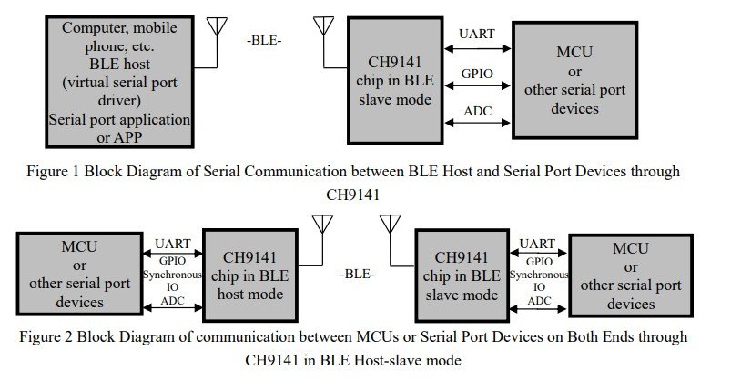
Communication diagram of the CH9141 chip
Basics
The basic circuit is relatively simple. The sender (host/master) BT module is connected to my CH32V006K8U6 board’s USART2 port. I had to remap the USART2 pins in my code, so this is a good occasion to show how it is done. The remapped pins are PD2 (TX) and PD3 (RX). This is a so-called partial remap, and in MounRiver Studio, it can be done by a single line because there are already prepared macros for it:
GPIO_PinRemapConfig(GPIO_PartialRemap3_USART2, ENABLE);
The macro itself is for the GPIO_PartialRemap3_USART2, which translates into 0x08240030. Here, we can see that there is a digit “3” which is exactly 011 when it is translated to binary. So, this is how we would know which PartialRemap should be selected from the macros. Another example: GPIO_PartialRemap5_USART2 is 0x08240050, thus we look for ‘5’, which is 101, and that would mean that PC4 is TX and PD1 is RX.
I also used PD4 as a generic push-pull output pin to control the AT pin on the sender. This way, I can configure the sender when the microcontroller starts and then switch to serial mode so that I can send messages to the receiver.
The BT module operates at 3.3V, so the VDD pin is connected to the common 3.3V rail. The CH32 gets its power from the USB, and then I use its 3.3V pin to feed all the other components in the project. The SLP pin of the BT module is also connected to the 3.3V rail - this keeps the module awake. And then obviously, the GND pin is connected to the common ground rail.
On the receiver side, the situation is almost the same; however, I used a CH32V003F4P6 development board.
I used USART1 (PD5 - TX, PD6 - RX) pins to communicate with the receiver BT module. Plus, I added a resistor and an LED to PD3 to demonstrate that I can send a message to the receiver and make the microcontroller toggle a certain pin.

Possible remapping of USART 2 pins

Test setup for the 2-way Bluetooth communication
Receiver
First, I explain the receiver, because the code is easier and it also makes more sense logically, because, for example, we need to know the MAC address of the receiver in order to be able to communicate with it from the sender.
I assigned two kinds of functions to the receiver. When it receives a certain, predefined command (!A), it toggles the previously-mentioned PD3 pin. This is very easy feedback to see that the code works because as soon as we send this specific command to the receiver, the LED on PD3 will toggle. This function (pin toggling) will also be useful for the upcoming project that will be built on the knowledge I summarise here.
Then, another type of command will make the receiver send back a predefined text. This is a “simulated" weather station, and one can request temperature (!T), humidity (!H) and pressure (!P) data from the receiver. Of course, I did not hook the MCU up with these sensors because to do so, I would need a separate article for it, but it still helps to demonstrate these things.
Then, finally, if we just send a random text, the receiver echoes back the exact same text to the sender. So, with this, I can demonstrate the two-way communication as well.
So, the processLine() function takes care of the above-described things. The function is placed in the main loop of the code, and it runs when the incoming data contains a newline character (‘\n’), which is supposed to be the end of the message. First, the code checks if the first character is an exclamation mark. If it is an exclamation mark and the message is at least 2 characters long, then the code passes the second character of the message to the cmd variable. This second character is supposed to be the unique, predefined command that we send from the sender, and it matches a certain action on the receiver side.
As mentioned earlier, when the “!A” message is received, the PD3 pin is toggled. The line just reads the current state of the PD3 pin, inverts it, and writes it back to the PD3 pin. Well, it toggles the pin.
The “!T” message is sending back a message that says “Temperature 23 \r\n”. Ideally, we’d have a temperature sensor, and this line would return the most recent value of that sensor, but I did not want to “distract” this project with adding more stuff, so I just simulated the behaviour by sending some text. “!H” and “!P” have a similar behaviour, but with some other text. And, if the user manages to send something else than these four characters, the device returns with a generic message that says unknown command. Finally, if the user by chance only sent an exclamation mark, another error message pops up, which says missing command.
If the first character of the message from the sender was not an exclamation mark, the message is treated as a message that should be echoed back to the sender. So, we simply sandwich the content of the RX buffer between a text that says “ECHO: “ and a CRLF ending, so the sender (which is now a receiver) knows where the message ends. So, ideally, when we send a string, a text, to the receiver, the sender should receive the same thing, and it should print it on the PC’s serial terminal.
As you could see, the above demonstration shows that we can both do something locally on the receiver, such as toggling a pin, or we can do something locally and then send back a response to the sender. For example, receive a command, process some data and send the results back. This way, I demonstrated both unidirectional and bidirectional communication.
Sure enough, to make the above function work, something must receive the messages from the BT module via USART and then fill the RX buffer up. I simply dropped a while() loop in the main loop because the MCU does not have anything critical to do, so we can just poll the serial port.
So the while() loop checks the RXNE flag, which is the “receive not empty” flag. While the receive contains something, the flag will stay 1 (SET, or true), so the while() loop will run.
In each iteration, we fetch a byte (a single character) from the USART port. We don’t care about the CR (carriage return (‘\r’)) character, but we do care about the LF (linefeed (‘\n’)) character, and if the code reaches it while reading from the USART, we run the above-introduced processLine() function. The counter rxi is reset at this point, so the next incoming data starts to fill up the buffer from the beginning.
If the incoming character was neither a CR nor an LF, it was then a regular character. Therefore, if we are still within the bounds of the size of our RX buffer (RXBUF_SZ), we add the character to the buffer and increment the pointer to the next position in the buffer, so the next iteration will place the next character in the (i+1)th position.
Otherwise, if we ran out of space, an error is thrown. So this while() runs endlessly and polls the USART for new received data. The data is collected in the buffer until the linefeed character arrives, and then the content of the buffer is processed by the processLine() function, which will respond to the content of the buffer in some way.
static void processLine(void)
{
    if(rxi == 0)
    {
        return;
    }
    rxbuf[rxi] = 0;
    if(rxbuf[0] == '!')
    {
        if(rxi >= 2)
        {
            char cmd = rxbuf[1];
            switch(cmd)
            {
                case 'A':
                    GPIO_WriteBit(GPIOD, GPIO_Pin_3, (BitAction)!GPIO_ReadOutputDataBit(GPIOD, GPIO_Pin_3));
                    send_usart1("OK: toggled\r\n");
                    break;
                case 'T':
                    send_usart1("Temperature: 23\r\n");
                break;
                case 'H':
                    send_usart1("Humidity: 65\r\n");
                break;
                case 'P':
                    send_usart1("Pressure: 1010\r\n");
                break;
                default:
                    send_usart1("ERR: unknown cmd\r\n");
                    break;
            }
        }
        else
        {
            send_usart1("ERR: missing cmd\r\n");
        }
    }
    else
    {
        send_usart1("ECHO: ");
        send_usart1(rxbuf);
        send_usart1_crlf();
    }
}
 while(USART_GetFlagStatus(USART1, USART_FLAG_RXNE) != RESET)
 {
      uint8_t receivedByte = USART_ReceiveData(USART1) & 0xFF;

      if(receivedByte == '\r')
      {
          continue;
      }
      else if(receivedByte == '\n')
      {
          processLine();
          rxi = 0;
      }
      else
      {
          if(rxi < RXBUF_SZ - 1)
          {
              rxbuf[rxi++] = (char)receivedByte;
          }
          else
          {
              rxi = 0;
              send_usart1("ERR: overflow\r\n");
          }
      }
}
Sender
The sender is a bit more cumbersome. First, it had to set up the connection with the receiver. So, we need to apply some AT commands, and then we can continue to the main code that is able to send and receive data. The biggest difference between the sender’s and the receiver’s code is that the sender not only receives and sends data via the USART peripheral that communicates with the BT module, but it also has an additional USART peripheral towards the computer. For example, when the receiver responds, we can see the response on the serial terminal on the PC. This means that the receiver MCU sends some text to its BT module, then the sender’s BT module receives this text and sends it to the corresponding USART. Then, this package is stored and passed to the other USART that bridges the MCU with the PC. And, the same goes the other way, so when I type something into my PC serial terminal, the text goes through the corresponding USART, and it gets passed to the other one, which then pushes it to the BT module and then the module sends it to the receiver’s BT module, which then finally forwards it to the receiver MCU’s USART.
To distinguish between AT command mode and data mode, the AT pin must be pulled LOW. So, when I configure the sender’s BT module, I sandwich the configuration lines between two GPIO pin toggling (PD4). Therefore, in my Bluetooth initialisation function, I start by pulling PD4 LOW, which is the GPIO pin of the MCU connected to the AT pin of the module. I let the pin settle, then I arm the USART2 receive buffer and relevant variables, and then I send a predefined AT command to the USART2 (BT module). Then I wait for the response and print it on USART1, which is the communication line between the MCU and my PC.
The “AT+HELLO?” is just a simple “ping” command to see if the BT module responds. In my case, it should respond “WELCOME”.
Then I want to check the BLE mode. This was already discussed in the beginning: if the response is 0, the module is in broadcast mode; if it is 1, it is in host mode (this is what we want), and if it is 2, then it is in device (slave) mode.
Then I want to check the name. This is done by inquiring it using the “AT+NAME?” command. The response would be “SENDER” in my case, because I named the device “SENDER”.
Then I want to connect to the receiver. It is important to know its MAC address in advance, and in a few lines, I show how it can be inquired. But, the command is very clear: “AT+CONN=7B:49:69:7B:54:50”. Right after this command, we need to see if the device managed to connect to the receiver by inquiring the status using the “AT+BLESTA?” command. This is a host device, so we can have 5 different responses: 00: not initialised, 01: scanning, 02: connecting, 03: successfully connected, 04: disconnecting. Obviously, we need to get “03” as the answer to be sure that the two devices are connected.
Finally, we print is device’s MAC address using the “AT+MAC?” command and then exit the AT command mode by pulling PD4 high.
When I was getting the MAC of the receiver, I simply plugged the receiver board into my sender’s microcontroller and ran these few lines at the beginning of the code and put an infinite loop after it. After arming the RX buffer and preparing the relevant variables, I sent an AT command that sets the name of the device. Then I waited for the response and inquired about the name of the device. The serial terminal printed “RECEIVER” successfully.
Some commands, like BLEMODE, require resetting the BT module. So, if you set “AT+BLEMODE=1” and it was let’s say 2 before, the device will still return 2 as an answer. To save the new setting in the non-volatile memory of the BT module, it must be restarted using the “AT+RESET” command. This will update the new values and modes when applicable.
void initialize_Bluetooth()
{
    GPIO_WriteBit(GPIOD, GPIO_Pin_4, Bit_RESET);

    Delay_Ms(500);
    USART2_RxArm();
    UART_SendString(USART2, "AT+HELLO?\r\n");
    waitForBufferAndPrint();

    printf("\nBLEMODE: ");
    UART_SendString(USART2, "AT+BLEMODE?\r\n");
    waitForBufferAndPrint();

    printf("\nName: ");
    UART_SendString(USART2, "AT+NAME?\r\n");
    waitForBufferAndPrint();

    printf("\nConnecting to receiver...");
    UART_SendString(USART2, "AT+CONN=7B:49:69:7B:54:50\r\n");
    waitForBufferAndPrint();

    printf("\nBLESTA: ");
    UART_SendString(USART2, "AT+BLESTA?\r\n");
    waitForBufferAndPrint();

    printf("\nMAC: ");
    UART_SendString(USART2, "AT+MAC?\r\n");
    waitForBufferAndPrint();

    GPIO_WriteBit(GPIOD, GPIO_Pin_4, Bit_SET);
}
GPIO_WriteBit(GPIOD, GPIO_Pin_4, Bit_RESET);
Delay_Ms(500);
USART2_RxArm();
UART_SendString(USART2, "AT+NAME=RECEIVER\r\n");
waitForBufferAndPrint();
printf("\nNAME: ");
UART_SendString(USART2, "AT+NAME?\r\n");
waitForBufferAndPrint();
GPIO_WriteBit(GPIOD, GPIO_Pin_4, Bit_SET);
while(1){}
So, first, let’s see how a string is sent to the USART. The function is universal, so we can use it to send messages to both USART1 and USART2 peripherals. It is just a simple while loop that iterates through the characters passed to it by advancing the pointer in each iteration. Technically, it is just sending bytes (char) step-by-step whenever the transmit data register (TXE) becomes empty. Once the TXE is empty, the next byte is sent to the selected USART peripheral using the built-in USART_SendData() function.
Receiving the data is a bit more complex, but it is not difficult. For educational purposes, I used an interrupt-based approach to deal with the data coming from USART2.
Basically, whenever new data comes, the interrupt is triggered. Then, we read this byte in from the corresponding data register and pass it to the receivedByte variable.
We want to read the message until it is complete, and its completion is indicated by the new line (“\n”) character. When this character arrives later, the U2_RxDone variable is changed to 1, but until then, it is 0, so we can enter the first if() block.
Then we check if the number of fetched bytes (value of the counter) is below the maximum capacity of the buffer. If so, we enter the next if() block and add the received byte to the buffer and advance the counter, so when the next item comes, it will be placed in the next place in the array that holds the received bytes.
Then, we check if this recently received character was “\n” or if we are about to exceed the capacity of the buffer. If either is true, we indicate that the buffer is ready to be read and we disable/disarm the interrupt, so it won’t fire and overwrite the contents of the buffer until we fetch it.
So, the basic principles are actually fairly simple. When the interrupt is fired, we read in the queuing byte and place it in the buffer. We do this until we get to the endline character, and then we let the other parts of the code know that now it is possible to fetch the contents of the (full/populated) buffer.
Then, after populating the RX buffer with the data coming from the USART2 (BT module), we need to get everything on the PC’s serial terminal (USART1). I did not want to directly use the RX buffer in case a new message arrives while the other USART uses it. So, I have a function that copies the contents of the RX buffer and then later on I use this copy.
The function is constantly polled in the main loop of the code. If the RX buffer is not full or populated, the code skips the rest of the function. Otherwise, we check the length of the buffer and, as a safety measure, to avoid overflow, maximise the value of n as the size of the buffer that we use for copying the RX buffer.
Then, using the memcpy(), I just pass the RX buffer to the destination buffer, and I add the null terminator to the end. This is why we counted until “destination_size - 1” before. We need that extra one character for the null-terminating character.
Finally, we replace the trailing character with a null-terminating character and return the length of the message.
Then, the usage is fairly simple: We fetch the n (length) and see if it is nonzero. If so, we print its contents to USART1 using the printf() function, and then we rearm the RX buffer. Remember, until fetching a copy of the RX buffer, the USART2 interrupt is disabled, so that’s why the USART2 must be rearmed then.
uint16_t n = copyUSART2Buffer(line, sizeof(line));
if (n)
{
    printf("%s\r\n", line);
    USART2_RxArm();
}
void UART_SendString(USART_TypeDef* USARTx, const char *s)
{
    while(*s)
    {
        while(USART_GetFlagStatus(USARTx, USART_FLAG_TXE) == RESET);
        USART_SendData(USARTx, *s++);
    }
}
void USART2_IRQHandler(void) __attribute__((interrupt("WCH-Interrupt-fast")));

void USART2_IRQHandler(void)
{
    if(USART_GetITStatus(USART2, USART_IT_RXNE) != RESET)
    {
        uint8_t receivedByte = (uint8_t)(USART2->DATAR & 0xFF);
        if (!U2_RxDone)
        {
            if (U2_RxCnt < U2_RX_MAX)
            {
                U2_RxBuf[U2_RxCnt++] = receivedByte;
            }
            if (receivedByte == '\n' || U2_RxCnt >= U2_RX_MAX)
            {
                U2_RxDone = 1;
                USART_ITConfig(USART2, USART_IT_RXNE, DISABLE);
            }
        }
    }
}
static uint16_t copyUSART2Buffer(char *destination, uint16_t destination_size)
{
    if (!U2_RxDone){ return 0;}
    uint16_t n = (U2_RxCnt < (destination_size - 1)) ? U2_RxCnt : (destination_size - 1);

    memcpy(destination, U2_RxBuf, n * sizeof(U2_RxBuf[0]));
    destination[n] = '\0';

    while (n && (destination[n-1] == '\r' || destination[n-1] == '\n'))
    {
         destination[--n] = '\0';
    }
    return n;
}
Rearming the RX buffer consists of the following steps:
Emptying the buffer by replacing all of its content with zeroes
Resetting the counter to zero
Resetting the “done flag”
Restarting the interrupt to enable new incoming data from USART2
Whenever we interact with USART2’s RX buffer, we must re-arm it, so it can keep accepting new data.
Once we send a message to USART2 and we expect a response, we need to fetch it. I put together the waitForBufferAndPrint() function for this. This is somewhat similar to the copyUSART2Buffer() function, but this function is not expected to be called in the main loop of the code. This function is specifically made to handle the messages during the configuration/initialisation phase of the code.
The code waits for the buffer to be populated and then directly prints the buffer on USART1 using the printf() function. Since the BT module sometimes sends an extra line of message (typically “OK” or similar) when it is used in AT command mode, I wanted to flush that crap away. So the quickFlushLeftover() does exactly that. It waits until the RX buffer is filled up again, or if nothing else arrives for 120 milliseconds and then rearms the RX buffer.
Use my affiliate links to buy the relevant products
void USART2_RxArm(void)
{
    for (uint16_t i = 0; i < U2_RX_MAX; i++)
    {
        U2_RxBuf[i] = 0;
    }
    U2_RxCnt = 0;
    U2_RxDone = 0;
    USART_ITConfig(USART2, USART_IT_RXNE, ENABLE);
}
void waitForBufferAndPrint()
{
    while(!U2_RxDone){}
    printf("%s\r\n", U2_RxBuf);
    quickFlushLeftover(120);
    USART2_RxArm();
}