USB PD Decoy breadboard power supply
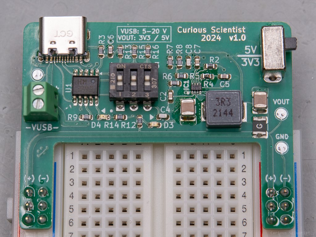
In this article, I show you my new creation. It is a USB PD decoy-based breadboard power supply. All the breadboard power supplies I have seen or encountered so far are utter garbage. All of them are based on LDOs (Low-dropout voltage regulators), and they can’t provide high voltage or large currents. My project aims to change the status quo of the breadboard power supplies and to introduce a new approach.
Introduction
So, as I said in the headline, my aim is to introduce a different approach to the breadboard power supplies. The devices I have encountered so far are based on the same 5 V and 3.3 LDO regulators (typically, AMS1117), they have a limited input voltage, and usually, the high voltage that goes to the LDOs is not accessible on the boards. Sometimes they don’t even have a simple fuse on the LDO’s output to protect the circuit from overcurrent which is being powered from the supply board.
Now here’s my idea: USB PD adapters are all over the place nowadays and everyone is using USB-C cables. For example, IKEA has a super cheap 30 W power adapter with PD 3.0 protocol. But also most of the mobile chargers, power supplies…etc. have some sort of PD power source nowadays.
This leads to my approach that I designed a circuit whose input is supplied by a PD adapter. In order to negotiate the supply voltage, I picked a WCH’s CH224K USB PD decoy chip. It is cheap, it requires very few external parts, it has built-in MOSFETS and it is very easy to select VUSB, the requested voltage from the power supply. After the USB PD chip selection, the next step is the DC-DC converter selection. I wanted to avoid using LDOs because they are not too efficient, they have lower maximum output current, and due to their working principles, they don’t like high input voltages. This is due to the fact that the voltage difference between the input voltage and the output voltage has to be dissipated as heat. So, if the input voltage is 12 V and the output voltage is 3.3V, 8.7 V times the current (let’s say 1 A because we use a lot of power for reasons) is turned into (waste) heat. 8.7 W is quite some heat. So, buck converters are much better because they use high-frequency switching instead of dissipating heat.
The original idea was to use the MP2315 buck converter chip because there’s a very nice little voltage regulator available on the market based on this chip. However, when I looked the chip up on Mouser, I was told that this chip is not recommended for new designs. So, I looked for an alternative and found the MP2393GTL-Z chip. Same chip (from my perspective) and it apparently works with the same components as the MP2315 which is very good. I looked at the datasheet of the MP2393 chip and drew a schematic based on it. I redesigned the feedback circuit in a way that with the help of a switch, I can switch between 3.3 V and 5.5 V output voltage. Perfect for microcontrollers. I also slapped a polyfuse on the output of the buck converter, so if something goes wrong with the rest of the circuit, there’s maybe a chance to save it from burning. This converter is no joke, when it is running at its peak performance, it is able to supply 3 A. Impressive!
Design considerations
So, the board is powered via a USB-C cable which is connected to a PD-capable USB charger. The voltage requested from the USB charger can be set by a 3-position DIP switch.
It can be 5 V, 9 V, 12 V, 15 V and 20 V. I do not recommend 5 V unless you strictly want to use 3.3 V at the output of the buck converter. Otherwise, the buck converter won’t be able to create 5 V on the outputs when the input voltage is also 5 V.
And here comes a nice trick. If we look at the IKEA charger I mentioned earlier, then we can see that the charger can provide 3 A at 5 V and 9 V, 2.5 A at 12 V, 2 A at 15 V and 1.5 A at 20 V. Why should not we take advantage of this? What I mean is that we could tap into the USB voltage (VUSB trace) and supply it to something power-hungry, such as a motor driver or a larger display (DWIN link). Let’s say, we use a 5 V microcontroller and connect a bunch of sensors and a display to it, so the total power consumption is 1 A at 5 V or 5 W. We still have 25 or so Watts available on the USB (assuming we use the IKEA charger and we requested 12 V).
For example, there’s still 2 A available if we selected 12 V as VUSB. Perfect! We can add a NEMA 17 stepper motor to the project and use it properly. Or, we can add a servo motor and supply it from the breadboard power supply’s screw terminal specifically made for this purpose. Or, why not power a large LED matrix or Neopixel board? If we have a lot of power available, the whole thing becomes so easy! There’s no need for an additional wall adapter and dangling cables all over the place. There are no forgotten ground connections between the externally powered device and the microcontroller because the ground is already unified on the board. What else do you need?
Additional resources
Below you can find all the resources, go to my PCBWay project page and grab it from there:
If you found this project fun, please consider supporting me by becoming a member of my YouTube channel.
Consider purchasing the relevant parts using my affiliate links.


