TCA9548A i2C multiplexer
In this video I show a nice device that can help us to use multiple i2C circuits with the same i2C address. There are circuits which have fixed i2C addresses, which means that you can only use one of them on a selected i2C bus. If you try to connect several of them, there will be a conflict on the bus and you would not be able to use them. This multiplexer (MUX) resolves this issue and allows you to use 8 devices with the same address at the same time. The way it works is very simple: first we select which channel we want to use by sending a command to the MUX, then we access the i2C device which is connected to the selected channel.
Schematics
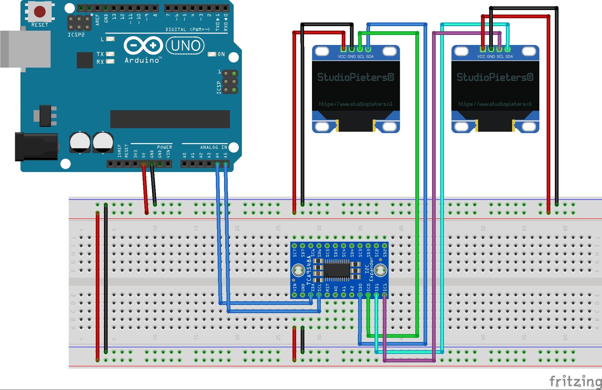
The TCA9548A multiplexer (MUX) is connected to the Arduino’s i2C pins (A4-SDA and A5-SCL). Then, the devices with the same addresses are connected to the SD0/SC0-SD7/SC7 channels of the MUX. You can use any voltage between 1.8-5 V, but always make sure that your i2C devices support 5 V! If the address of your i2C devices is between 0x70 and 0x77, you have to change the address of the MUX by changing the A0, A1, A2 pins.
Arduino code
//Arduino Uno; SDA = A4, SCL = A5
#include <Wire.h>

int counter1 = 0; //counter for display 1
int counter2 = 0; //counter for display 2
int displayCounter = 0; //counter for selecting displays

//--Display---------------------------------------------
#include <Adafruit_GFX.h>
#include <Adafruit_SSD1306.h>

#define SCREEN_WIDTH 128 // OLED display width, in pixels
#define SCREEN_HEIGHT 64 // OLED display height, in pixels
#define OLED_RESET     4 // Reset pin
Adafruit_SSD1306 display1(OLED_RESET);
Adafruit_SSD1306 display2(OLED_RESET);

void setup()
{
    switchDisplay();
    display1.begin(SSD1306_SWITCHCAPVCC, 0x3C);
    display1.setTextSize(4);
    display1.setTextColor(SSD1306_WHITE);
    delay(300);
    //
    switchDisplay();
    display2.begin(SSD1306_SWITCHCAPVCC, 0x3C);
    display2.setTextSize(4);
    display2.setTextColor(SSD1306_WHITE);
}

void loop()
{
  switchDisplay();
  printDisplay1();
  delay(250);
  switchDisplay();
  printDisplay2();
  delay(250);
}

void printDisplay1()
{
  display1.clearDisplay();     // Clear display
  display1.setCursor(0, 0);    // Start at top-left corner
  display1.print(counter1);
  display1.display();
  counter1++;
}

void printDisplay2()
{
  display2.clearDisplay();    // Clear display
  display2.setCursor(0, 0);   // Start at top-left corner
  display2.print(counter2);
  display2.display();
  counter2++;
}

void switchDisplay()
{
  if(displayCounter == 0) //the code enters this part after powering the arduino
  {
    Wire.beginTransmission(0x70); //connect to the MUX
    Wire.write(1 << 0); //write the pins [SD0,SC0]
    Wire.endTransmission();
    //
    displayCounter = 1;
    //update the value, so the code enters the below part at the next iteration
  }
  else
  {
    Wire.beginTransmission(0x70);
    Wire.write(1 << 1);//[SD1,SC1]
    Wire.endTransmission();
    //
    displayCounter = 0;
    //update the value, so the code enters the first part at the next iteration
  }
}