Building an SZBK07-based thermostat for Peltier cooling
In this video I show you my DIY thermostat. The thermostat is based on the popular SZBK07 DC-DC converter which provides power for a Peltier cooler. The SZBK07 DC-DC converter is controlled by a MCP41100 8-bit digital potentiometer. The whole thermostat is based on a self-regulating feedback logic. The cold side temperature of the Peltier cooler is measured with an NTC thermistor and based on the relationship between the measured temperature and the goal temperature the power for the Peltier cooler is either increased (T(goal) is smaller than T(measured)) or decreased (T(goal) is higher than T(measured)). The power remains unchanged if the temperature stays within a certain tolerance. The theoretical step size for the temperature ("resolution") is around 0.21°C.
Wiring diagram
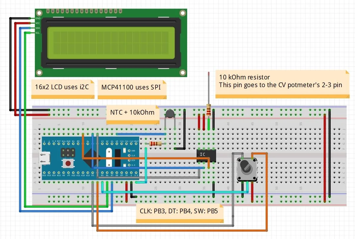
The MCP41100 uses SPI and the 16x2 LCD uses i2C communication. The rotary encoder uses the PB3 for CLK, PB4 for DT and PB5 for SW. The wiper of the MCP41100 is connected to the 10 kOhm resistor which is connected to the pin 2-3 of the CV potentiometer on the SZBK07 board. The NTC resistor is in a voltage divider configuration with a 10 kOhm resistor. The input voltage of the divider is +3.3 V and the Vout of the voltage divider is measured on the A0 pin. The MCP41100 is giving +5V by default when the bit value is 0. By increasing the bit value, the output voltage of the digital potentiometer drops.
Arduino/STM32 source code
//STM32-based digital thermostat
#include <SPI.h> //SPI comunication
//SPI on STM32: MOSI: PA7, SCK: PA5
//SPI on Arduino: MOSI: 11, SCK: 13

//16x2 LCD
#include <LiquidCrystal_I2C.h> //SDA = B7[A4], SCL = B6[A5] STM32/[Arduino]
LiquidCrystal_I2C lcd(0x27, 16, 2);

const byte CS1_pin = PA4; //CS pin for potmeter (Pick any on Arduino, Pin 10 is the "default")

float nominalVoltage = 0; //Calculated voltage, based on the 8-bit value
float setTemperature = 30; //Default set temperature (good idea to set it higher than the room temp)

int counter = 0; //counts the clicks of the of the rotary encoder, 0-255
int coolingPower = 0; // basically the value of the digital potmeter: 0-255
float tolerance = 0.5; //tolerance for the temperature

//Defining pins
const int RotaryCLK = PB3; //CLK pin on the rotary encoder
const int RotaryDT = PB4; //DT pin on the rotary encoder
const int PushButton = PB5; //Button to turn the heating on and off (SW of rotary encoder)
const int VoutPin = PA0; //ADC0 pin of STM32

//Statuses for the rotary encoder
int CLKNow;
int CLKPrevious;

int DTNow;
int DTPrevious;

// Time
float TimeNow1;
float TimeNow2; //For the LCD
float TimeNow3; //For the Thermostate

bool PSU_Enabled = false;

//Thermometer-related variables
float Vsupply = 3.3; //power supply voltage (3.3 V rail) - STM32 ADC pin is NOT 5 V tolerant
float Vout; //Voltage divider output
float R_NTC; //NTC thermistor resistance in Ohms
float R_10k = 9840; //10k resistor measured resistance in Ohms (other element in the voltage divider)
float B_param = 3700; //B-coefficient of the thermistor
float T0 = 298.15; //25°C in Kelvin
float Temp_K; //Temperature measured by the thermistor (Kelvin)
float Temp_C; //Temperature measured by the thermistor (Celsius)

void setup()
{
  pinMode(CS1_pin, OUTPUT); //Chip select is an output
  pinMode(PB3, INPUT_PULLUP); //RotaryCLK
  pinMode(PB4, INPUT_PULLUP); //RotaryDT
  pinMode(PB5, INPUT_PULLUP); //RotarySW
  pinMode(VoutPin, INPUT_ANALOG); //A0 pin for measuring the voltage of the NTC

  //------------------------------------------------------
  lcd.begin();                      // initialize the lcd
  lcd.backlight();
  //------------------------------------------------------
  lcd.setCursor(0,0); //Defining positon to write from first row,first column .
  lcd.print(" Digital SZKB07");
  lcd.setCursor(0,1); //Second row, first column
  lcd.print("    MCP41100 "); //You can write 16 Characters per line .
  delay(3000); //wait 3 sec
  //------------------------------------------------------
  //Store states of the rotary encoder
  CLKPrevious = digitalRead(RotaryCLK);
  DTPrevious = digitalRead(RotaryDT);

  attachInterrupt(digitalPinToInterrupt(RotaryCLK), rotate, CHANGE); //CLK pin is an interrupt pin
  attachInterrupt(digitalPinToInterrupt(PushButton), pushButton, FALLING); //PushButton pin is an interrupt pin
  //On STM32, you can pick any pin basically. On Arduino Uno and Nano, it is only Pin 2 and 3.

  TimeNow1 = millis(); //Start time
  digitalWrite(CS1_pin, HIGH); //Select potmeter
  SPI.begin(); //start SPI for the digital potmeter

  digitalWrite(CS1_pin, LOW);
  //Default value for the pot should be zero (otherwise, Vout will be 2.5 V by default)
  SPI.transfer(0x11);  //command 00010001 [00][01][00][11]
  SPI.transfer(0); //transfer the integer value of the potmeter (0-255 value)
  delayMicroseconds(100); //wait
  digitalWrite(CS1_pin, HIGH);
}

void loop()
{
  TimeNow2 = millis();

  if(TimeNow2 - TimeNow1 > 200) //update LCD every 200 ms
  {
    ConvertToTemperature(); //convert NTC voltage to temperature value
    printLCD(); //Update LCD

    TimeNow1 = millis();
  }

  if(TimeNow2 - TimeNow3 > 2000) //update PSU every 2 s (thermal "inertia")
  {
    writePotmeter(); //write the potmeter value in every loop

    if(PSU_Enabled == true) //If the PSU is enabled, we can change the potmeter
    {
      adjustTemperature(); //increase or decrease the value of the coolingPower variable
      TimeNow3 = millis();
    }
  }

}

void writePotmeter()
{
    //CS goes low
    digitalWrite(CS1_pin, LOW);

    SPI.transfer(0x11);  //command 00010001 [00][01][00][11]
    SPI.transfer(coolingPower); //transfer the integer value of the potmeter (0-255 value)
    delayMicroseconds(100); //wait
    //CS goes high
    digitalWrite(CS1_pin, HIGH);

    nominalVoltage = 5 - (coolingPower * 5.0 / 256.0); //5 V might not be 5.000 V exactly

}

void adjustTemperature()
{

  if(abs(Temp_C - setTemperature) < tolerance) //Diff is less than 0.5°C
  {
    //If we are within the tolerance, the coolingPower variable is not changed anymore.
  }
  else
  {
    if(Temp_C > setTemperature) //if the measured T > set temperature (goal temp)
    {
      if(coolingPower < 256)
      {
        coolingPower++; //this increases the power to the Peltier - more cooling
      }
      else
      {
        //do nothing after reaching the max. value of the digital potentiometer
      }
    }

    else //the measured T < set temperature (overcooling)
    {
      if(coolingPower > 0)
      {
        coolingPower--; //this decreases the power to the Peltier - less cooling
      }
      else
      {
        //do nothing after reaching the min. value of the digital potentiometer
      }
    }
  }

}

void ConvertToTemperature()
{
  Vout = analogRead(VoutPin)* (3.3/4095); //4095 - 12 bit resolution of the blue pill
  //For Arduino users: (5.0 / 1023)
  R_NTC = (Vout * R_10k) /(Vsupply - Vout); //calculating the resistance of the thermistor
  Temp_K = (T0*B_param)/(T0*log(R_NTC/R_10k)+B_param); //Temperature in Kelvin
  Temp_C = Temp_K - 273.15; //converting into Celsius
}

void rotate()
{
  CLKNow = digitalRead(RotaryCLK); //Read the state of the CLK pin

  // If last and current state of CLK are different, then a pulse occurred
  if (CLKNow != CLKPrevious  && CLKNow == 1){

    // If the DT state is different than the CLK state then
    // the encoder is rotating A direction: increase
    if (digitalRead(RotaryDT) != CLKNow) {
      if(counter < 256) //we do not go above room temperature (assumed to be 30C)
      {
        counter++; //increase counter by 1
        setTemperature = 30 - (55 * counter/256.0);
        //counter = 1 - we subtract 0.21 from 30
        //counter = 255 - we subtract 55 from 30 - higher counter, higher current, lower temperature
      }
      else
      {
        //Don't let it go above 255
      }

      } else {
      // Encoder is rotating B direction so decrease
      if(counter < 1) //we do not go below -25 (assumed to be the minimum T on the Peltier)
      {
       // Don't let it go below 0
      }
      else
      {
        counter--; //decrease counter by 1
        setTemperature = 30 - (55 * counter/256.0);
         //counter = 1 - we subtract 0.21 from 30
         //counter = 255 - we subtract 55 from 30 - higher counter, higher current, lower temperature
      }
    }
  }
  CLKPrevious = CLKNow;  // Store last CLK state
}

void pushButton()
{
  if(PSU_Enabled == false) //if the cooling was OFF
  {
    PSU_Enabled = true;  //turn it ON (writes the potmeter)
  }
  else //if the cooling was ON
  {
    PSU_Enabled = false; //turn it OFF (does not write the potmeter)
    //When you disable cooling, you might want to reset the values too!
    coolingPower = 0;
  }
}

void printLCD()
{
    //lcd.clear();
    lcd.setCursor(0,0); // Defining positon to write from first row, first column .
    lcd.print("P:");
    lcd.setCursor(2,0);
    lcd.print("    ");
    lcd.setCursor(2,0);
    lcd.print(coolingPower);    //print pot level (0-255)
    lcd.setCursor(6,0);
    lcd.print("V:");
    lcd.setCursor(8,0);
    lcd.print("     ");
    lcd.setCursor(8,0);
    lcd.print(nominalVoltage); //nominal output voltage on the MCP41100's output
    //Checking the PSU
    if(PSU_Enabled)
    {
      lcd.setCursor(13,0);
      lcd.print("   ");
      lcd.setCursor(13,0);
      lcd.print("EN");
    }
    else
    {
      lcd.setCursor(13,0);
      lcd.print("   ");
      lcd.setCursor(13,0);
      lcd.print("DIS");
    }
    //Second line
    lcd.setCursor(0,1); // Defining positon to write from second row, first column .
    lcd.print("T:");
    lcd.setCursor(2,1);
    lcd.print("     ");
    lcd.setCursor(2,1);
    lcd.print(Temp_C,1);    //Print the temperature in °C
    lcd.setCursor(7,1);
    lcd.print("ST:");
    lcd.setCursor(10,1);
    lcd.print("     ");
    lcd.setCursor(10,1);
    lcd.print(setTemperature,1);
}

/*
 *  Resistance formula
 *  R = 100 kOhm *(256-x)/256 + Rw
 *  Rw = 125 for the 100 kOhm
 *
 * Temperature resolution (everything is assumed to be perfect/ideal
 *
 * 256 steps are available in the MCP41100
 * The temperature difference between -25°C and +30°C is 55°C
 * 55/256 = 0.215 - resolution is 0.215°C/step
 *
 */