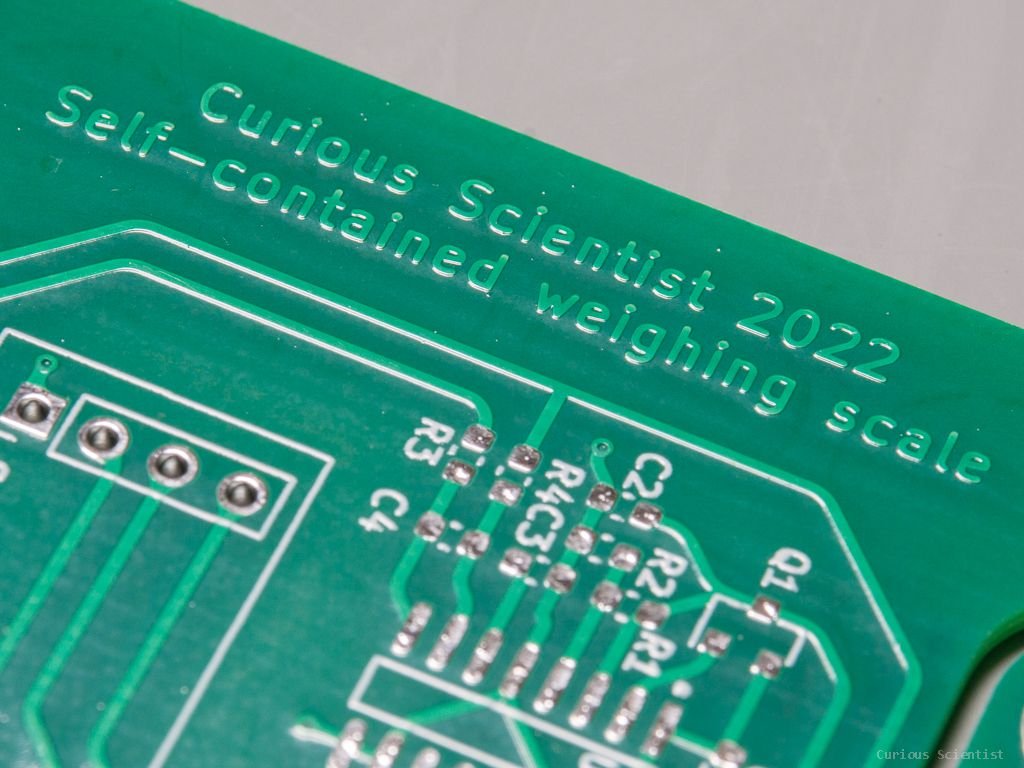
PCB weighing scale - A better version
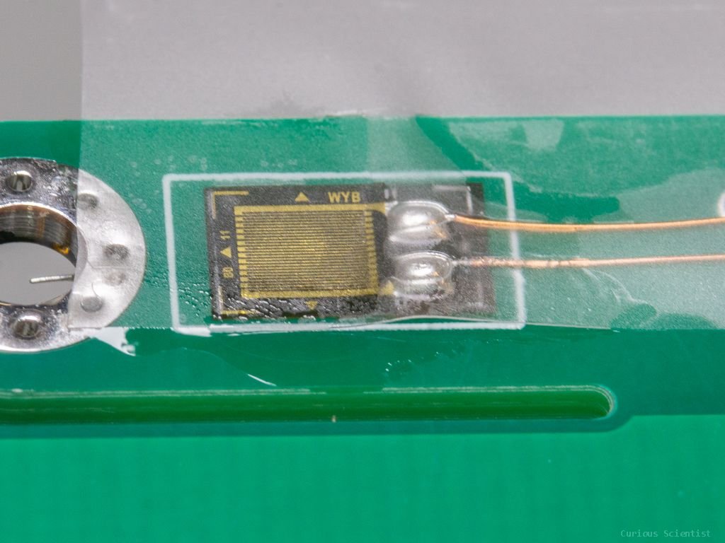
I recently published a project where I tried to utilize the traces on a PCB as a strain gauge in order to use the PCB as a weighing scale (or “bending load cell”). The concept was simple: I created a cantilever beam section on the PCB and I placed a pattern of copper traces on this bending part that is similar to the pattern of the conductive traces in a strain gauge. Unfortunately, the concept did not work, because the pattern had too low resistance and an even smaller change in resistance when the PCB was bent. However, when I put a strain gauge on the cantilever beam part, the concept worked perfectly. But, due to structural limitations, I could not measure more than 200-250 grams.
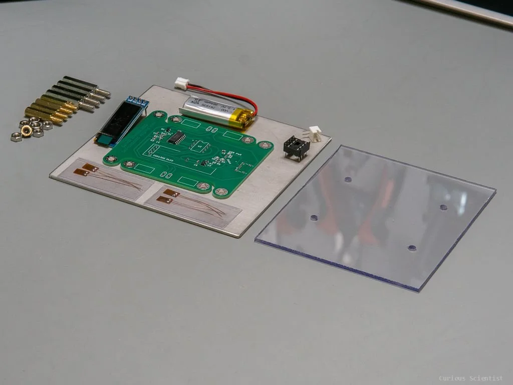
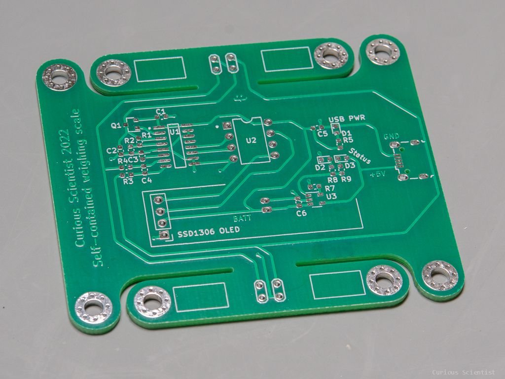
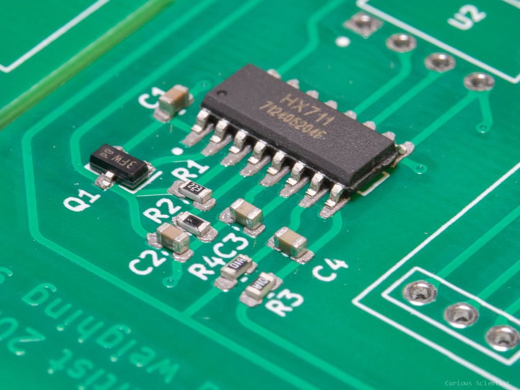
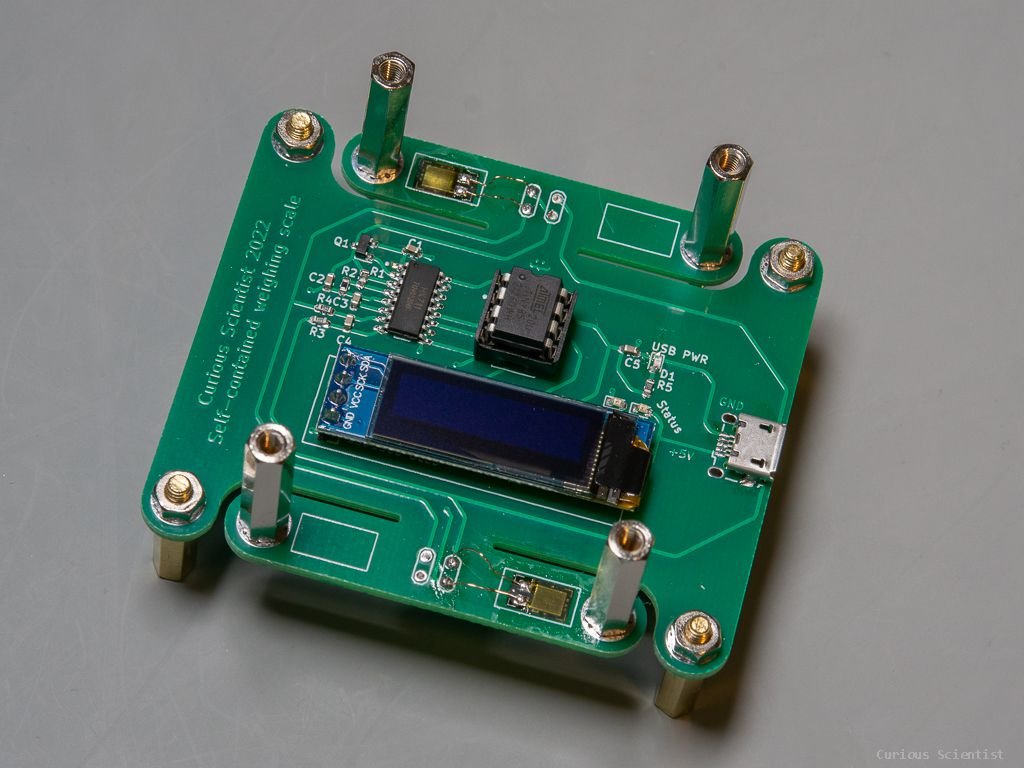
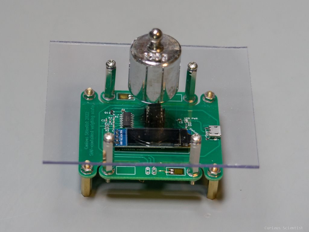
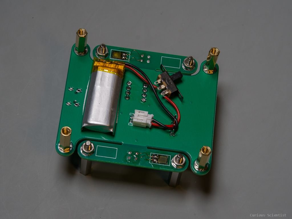
Therefore, I decided to reiterate the project and create a better version of this concept. Since I knew that the PCB traces won’t work, I kept using strain gauges in this design. I also replaced most of the circuitry. The whole Wheatstone bridge is now made of strain gauges (full bridge configuration). This bridge is then managed and measured by an HX711 module. The module is read by an ATTiny85 microcontroller and the results are printed on a small OLED display. The PCB also has a built-in LiPo battery with a charging circuit (MCP73831T).
Additional content
You can get some of the relevant products using these affiliate links:

Get my PCB from PCBWay!

Join my YouTube membership!
Calibration
After everything is up and running, the scale is still only providing raw data that is proportional to the applied load. This data does not have any units, therefore we must calibrate the scale to see the weight in some understandable units.
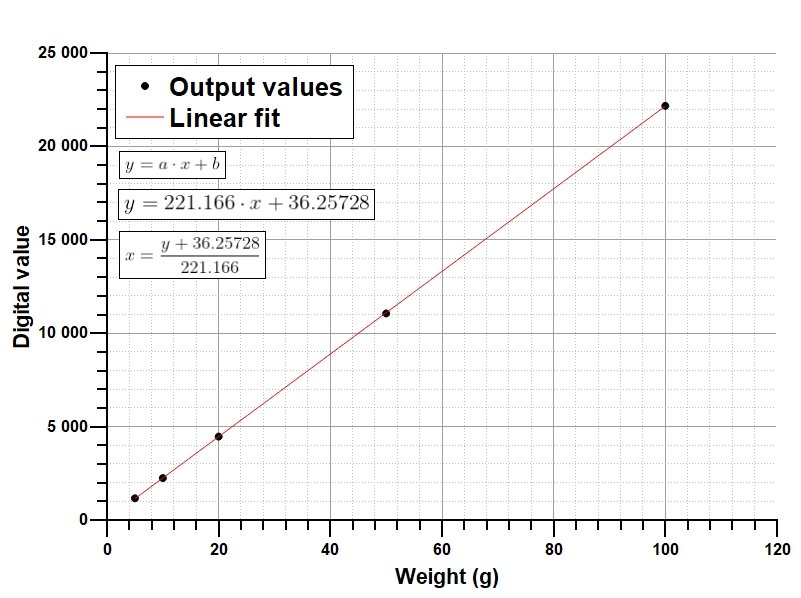
The output value is linearly proportional to the applied load. If we put two times more weight on the scale, the output value will be also two times higher. This linear relationship makes the calibration very simple.
The calibration is easy: we put a known weight on the scale, wait a bit to let things settle, and then we read the value given by the scale. We repeat this exercise with multiple different weights while trying to cover a large range of values. I did it with 5 different values and the values are shown in the table below.
| Weight (grams) | Output value |
|---|---|
| 5 | 1161 |
| 10 | 2244 |
| 20 | 4465 |
| 50 | 11057 |
| 100 | 22170 |
Then, we can grab our favourite plotting software (for me it is QtiPlot), and we fit a linear on this data. I chose the weight to be on the X-axis, and the output values on the Y-axis. By fitting the data, we get the A and B coefficients of the linear equation. Then we just rearrange the equation to X (weight) and substitute Y with the raw output values.
For example, if the reading was 34288, then by using the equation from the plot we get 155.23 g as weight.
Finally, we just implement the linear equation with the calibration coefficients in the code of the microcontroller and we get the weight directly.