CPU and RAM monitor, literally
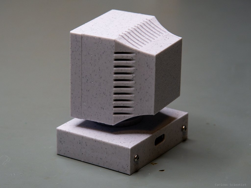
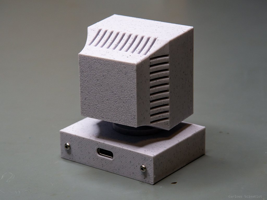
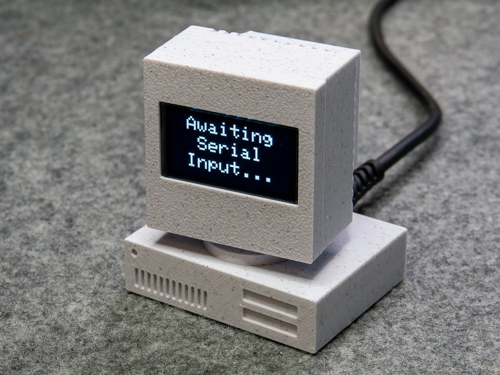
In this video, I show you how to build a cool gadget for your computer. I had an idea about a similar device (which I will discuss in another article) and then this device popped up in my mind. The basic concept is really simple: I designed and printed and old PC with a CRT monitor and a chassis, and then placed an OLED display in the CRT monitor and a microcontroller in the PC chassis. The device, in this demonstration, is used as a resource monitor that shows the CPU and RAM usage. Apart from 3D printing and a little soldering, some programming was needed, too. The programming consists of an Arduino code that receives the CPU and RAM usage data from the PC and puts in on the OLED display, and it also consists of writing a little C# code that sends this info to the microcontroller.
Introduction
The core of the device is my custom ATmega32U4 board, but basically, any microcontroller can be used that can connect to the computer via USB. It is a little overkill because I only use a fraction of the microcontroller’s peripherals, but I have many of these boards at home. The microcontroller does only two things: it receives data from the computer via USB and it prints this information on a 1.3” 128x64 pixels OLED display.
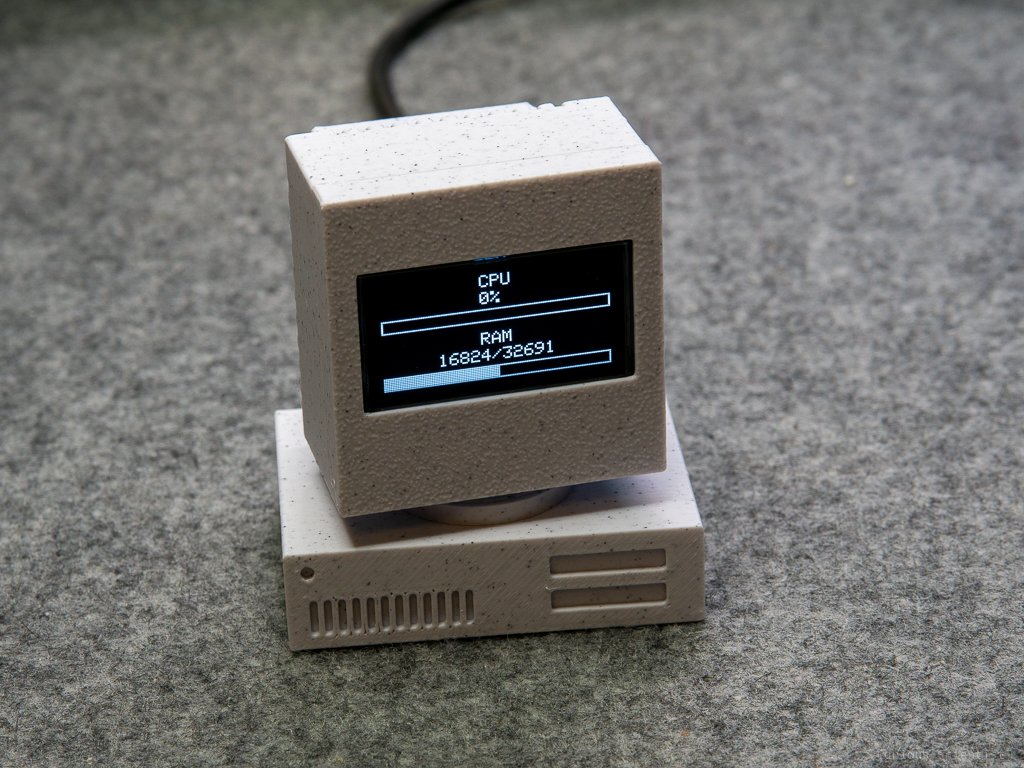
The Arduino software is relatively simple, it is barely 150 lines of code. The display is driven using an Adafruit library for the SH1106 display. The data which are being sent from the computer are the CPU usage (%), total RAM and available RAM. These three numbers are sent as comma-separated integers, for example, ”75,4096,3231”. Then, a simple script slices up the string into the three integers and passes them to their respective variables. The variables are then processed by the code that prints them on the OLED display as numerical values. Another piece of code takes these numerical values and draws horizontal “progress bars” on the display (one for the CPU, one for the RAM) whose lengths are proportional to the CPU/RAM usage.
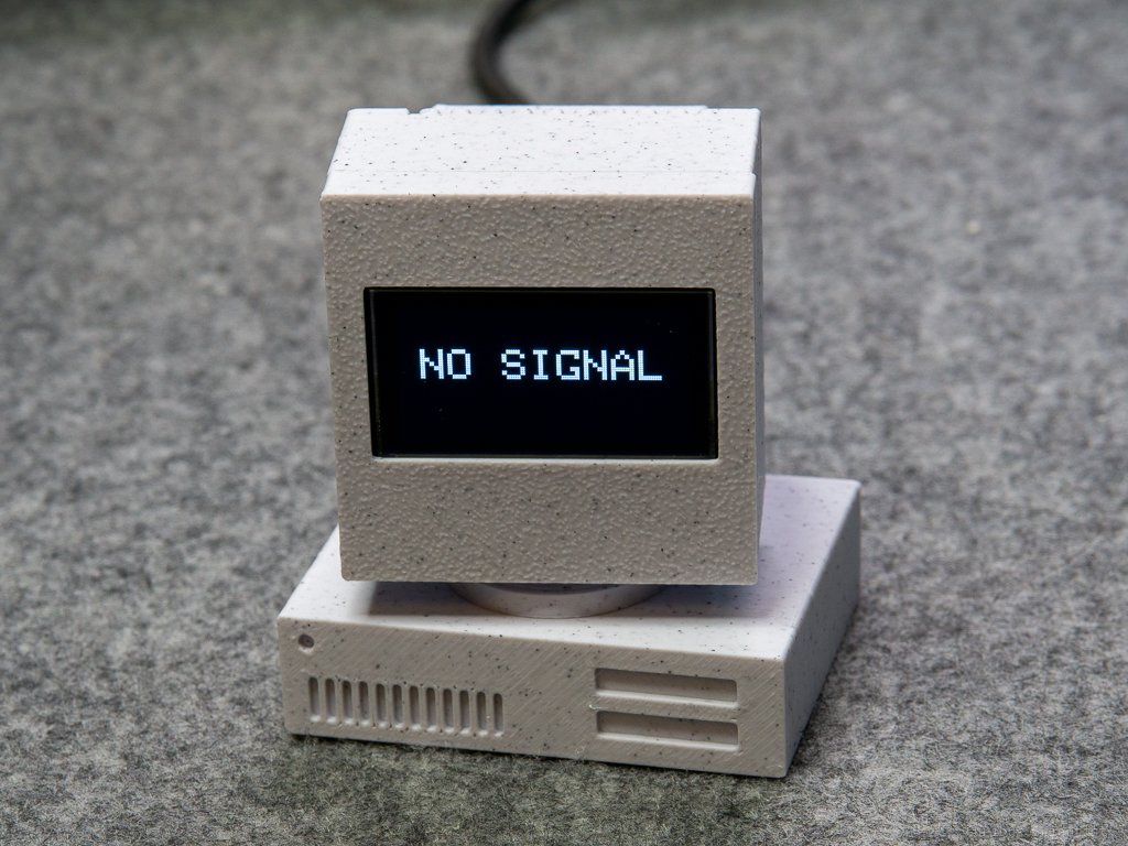
There are also two timers set up in case the user shuts down the computer. If there’s no new CPU/RAM usage value for 30 seconds (default update frequency is every 2 seconds) the display shows a “NO SIGNAL” message. This message is kept on the display for 15 seconds and then the display is shut down. When a new CPU/RAM usage value comes, the display automatically turns on and shows the data with the bars.
The C# software is also relatively simple, it is just a tiny window with a few numbers printed in it. A timer in the app ticks every 2 seconds and reads the current CPU and RAM usage. These numbers are printed on the UI of the software, and they are also sent to the COM port in the previously mentioned format (“75,4096,3231”). When the software is minimized, it does not show up among the tray icons, but only in the notification area to reduce unnecessary disturbance for the user. The software can be recalled from the notification area at any time.
The app is developed to be fully automated, however, this requires a little preparation in the beginning.
First, plug the device into a free USB port. Preferably, choose a port that won’t be used for anything else.
Go to the device manager and locate the device under the Ports (COM<P) drop-down list. Right-click on the device and open properties.
Go to Port Settings and open Advanced. At the bottom of the window, change the COM Port Number to COM69. It is very important that you choose COM69 because the C# software is specifically looking for this port.
Press OK on all windows, and disconnect the device from the computer.
Reconnect the device and check in the device manager if the device shows up under COM69.
If you want the device to automatically connect when you restart the computer, do the following steps:
Press Windows+R to open the Run terminal. Enter shell:startup and press Enter.
A folder will pop up. Copy the .exe file into this folder. This will make sure that the .exe will start when Windows starts.
Enjoy!
Additional resources
The Arduino code, the executable file and the 3D printing files are available for my YouTube members!
Please consider supporting me by becoming a member!
