Building a digital control circuit for the SZBK07 DC-DC buck converter
In this video I continue the previous video's experiment and show you how to control the SZBK07 DC-DC converter with a microcontroller and the MCP41100 digital potentiometer. With this technique, you can control the DC-DC converter with a digital controller. The rotary encoder is used to increase or decrease the value of the bit which is written on the digital potentiometer which results in a voltage between 0 and 5 V on the wiper of the digital potentiometer. With this voltage and with the help of a 10 kOhm resistor, we "inject" the current to the feedback pin of the buck controller and adjust the output voltage of the DC-DC controller. Due to the limited resolution (8 bit) of the MCP41100, the resolution of the output voltage of the DC-DC converter scales with the magnitude of the voltage. Lower voltage can be adjusted in much smaller steps. The maximum output voltage 36 V can be adjusted in 0.14 V steps while an output voltage of 10 V can be adjusted in 0.04 V steps.
Schematics
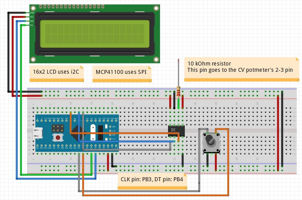
The project is built around an STM32 circuit which takes care of the rotary encoder, the 16x2 LCD and the MCP41100 8 bit digital potentiometer. The rotary encoder changes the value of a variable between 0-255 which is then forwarded to the MCP41100 and causes a change in the output voltage of the wiper. This output voltage is then goes to the pin 2 or 3 of the CV trimmer potmeter on the SZBK07 DC-DC converter through a 10 kOm resistor.

The 10 kOhm resistor from the left hand side picture is connected to the pin 2 or 3 of the CV trimmer potentiometer. They are connected together on the PCB, so it does not matter which pin you use.
STM32/Arduino source code
//STM32-based digital potmeter
#include <SPI.h> //SPI comunication
//SPI on STM32: MOSI: PA7, SCK: PA5
//SPI on Arduino: MOSI: 11, SCK: 13

//16x2 LCD
#include <LiquidCrystal_I2C.h> //SDA = B7[A4], SCL = B6[A5] STM32/[Arduino]
LiquidCrystal_I2C lcd(0x27, 16, 2);

const byte CS1_pin = PA4; //CS pin for potmeter (Pick any on Arduino, Pin 10 is the "default")

float nominalVoltage = 0; //Calculated voltage, based on the 8-bit value

int counter_1 = 0; //counter for the potmeter 1 - 0-255 bit value

//Defining pins
const int RotaryCLK = PB3; //CLK pin on the rotary encoder
const int RotaryDT = PB4; //DT pin on the rotary encoder

//Statuses for the rotary encoder
int CLKNow;
int CLKPrevious;

int DTNow;
int DTPrevious;

// Time
float TimeNow1;
float TimeNow2;

void setup()
{
 Serial.begin(9600); //serial communication
 Serial.println("SZKB07 digital control"); //message on serial port

 pinMode(CS1_pin, OUTPUT); //Chip select is an output
 digitalWrite(CS1_pin, HIGH); //Select potmeter

  //------------------------------------------------------
  lcd.begin();                      // initialize the lcd
  lcd.backlight();
  //------------------------------------------------------
  lcd.setCursor(0,0); //Defining positon to write from first row,first column .
  lcd.print(" Digital SZKB07");
  lcd.setCursor(0,1); //Second row, first column
  lcd.print("    MCP41100 "); //You can write 16 Characters per line .
  delay(3000); //wait 3 sec
  //------------------------------------------------------
  //Store states of the rotary encoder
  CLKPrevious = digitalRead(RotaryCLK);
  DTPrevious = digitalRead(RotaryDT);

  attachInterrupt(digitalPinToInterrupt(RotaryCLK), rotate, CHANGE); //CLK pin is an interrupt pin
  //On STM32, you can pick any pin basically. On Arduino Uno and Nano, it is only Pin 2 and 3.

  TimeNow1 = millis(); //Start time
  SPI.begin(); //start SPI for the digital potmeter
}

void loop()
{

   TimeNow2 = millis();
  if(TimeNow2 - TimeNow1 > 200) //update LCD every 200 ms
  {
    printLCD();
    TimeNow1 = millis();
  }

  writePotmeter(); //write the potmeter value in every loop

}

void writePotmeter()
{
    //CS goes low
    digitalWrite(CS1_pin, LOW);

    SPI.transfer(0x11);  //command 00010001 [00][01][00][11]
    SPI.transfer(counter_1); //transfer the integer value of the potmeter (0-255 value)

    delayMicroseconds(100); //wait
    Serial.print("counter_1: ");    //send the data to the computer
    Serial.println(counter_1);

    //CS goes high
    digitalWrite(CS1_pin, HIGH);

    //nominal voltage, based on the 5 V rail voltage and the counter_1 value
    nominalVoltage = counter_1 * 5.0 / 256.0; //5 V might not be 5.000 V exactly

}

void rotate()
{
  CLKNow = digitalRead(RotaryCLK); //Read the state of the CLK pin

  // If last and current state of CLK are different, then a pulse occurred
  if (CLKNow != CLKPrevious  && CLKNow == 1){

    // If the DT state is different than the CLK state then
    // the encoder is rotating A direction: increase
    if (digitalRead(RotaryDT) != CLKNow) {
      if(counter_1 < 256)
      {
      counter_1++; //increase counter by 1
      }
      else
      {
        //Don't let it go above 255
      }

    } else {
      // Encoder is rotating B direction so decrease
      if(counter_1 < 1)
      {
       // Don't let it go below 0
      }
      else
      {
      counter_1--; //decrease counter by 1
      }

    }
  }
  CLKPrevious = CLKNow;  // Store last CLK state
}

void printLCD()
{
    //lcd.clear();
    lcd.setCursor(0,0); // Defining positon to write from first row, first column .
    lcd.print("Pot level: ");
    lcd.setCursor(11,0);
    lcd.print("        ");
    lcd.setCursor(11,0);
    lcd.print(counter_1);    //Print the number of button clicks

    lcd.setCursor(0,1); // Defining positon to write from second row, first column .
    lcd.print("Voltage: ");
    lcd.setCursor(9,1);
    lcd.print("      ");
    lcd.setCursor(9,1);
    lcd.print(nominalVoltage);    //Print the number of pulses
}

/*
 *  Resistance formula
 *  R = 100 kOhm *(256-x)/256 + Rw
 *  Rw = 125 for the 100 kOhm
 * /
 */