Building a coil winder [Part 7] - New electronics
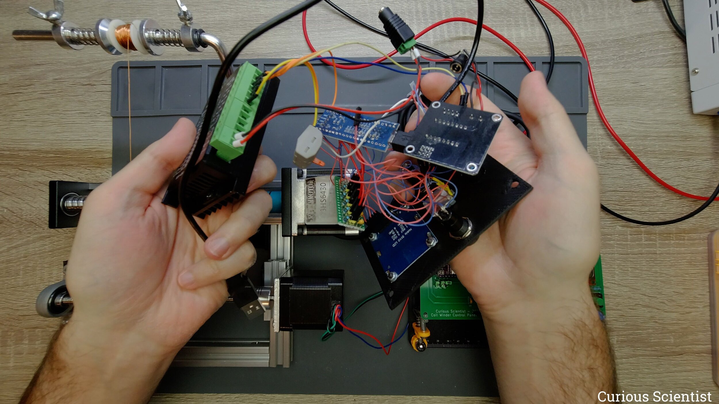
In this video I show you a big update - I replaced all the wires and weird connections to a custom made PCB. I designed my own PCB in KiCAD then ordered them from PCBWay. However, I made a small mistake in the design process and the pin header for the Nokia 5110 display is mirrored which means that the display should be connected upside-down to make it work. This is an easy fix since some libraries support the rotation of the text but the specific library that I use for the display (and the microcontroller) does not support it and it would be a large task to rewrite the whole software. I also wanted to make some other changes on the board, so I decided to redesign it and order a new PCB.
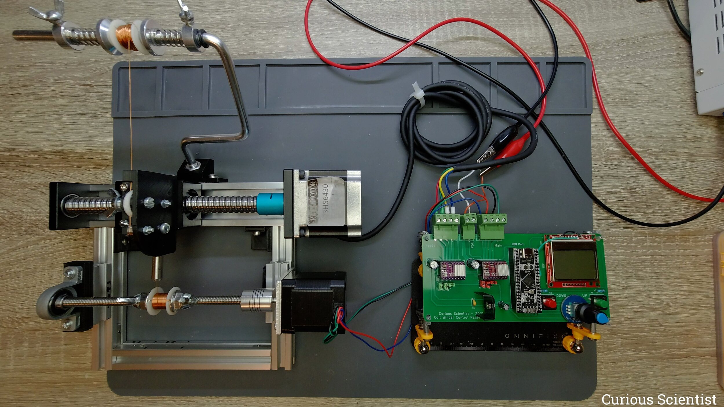
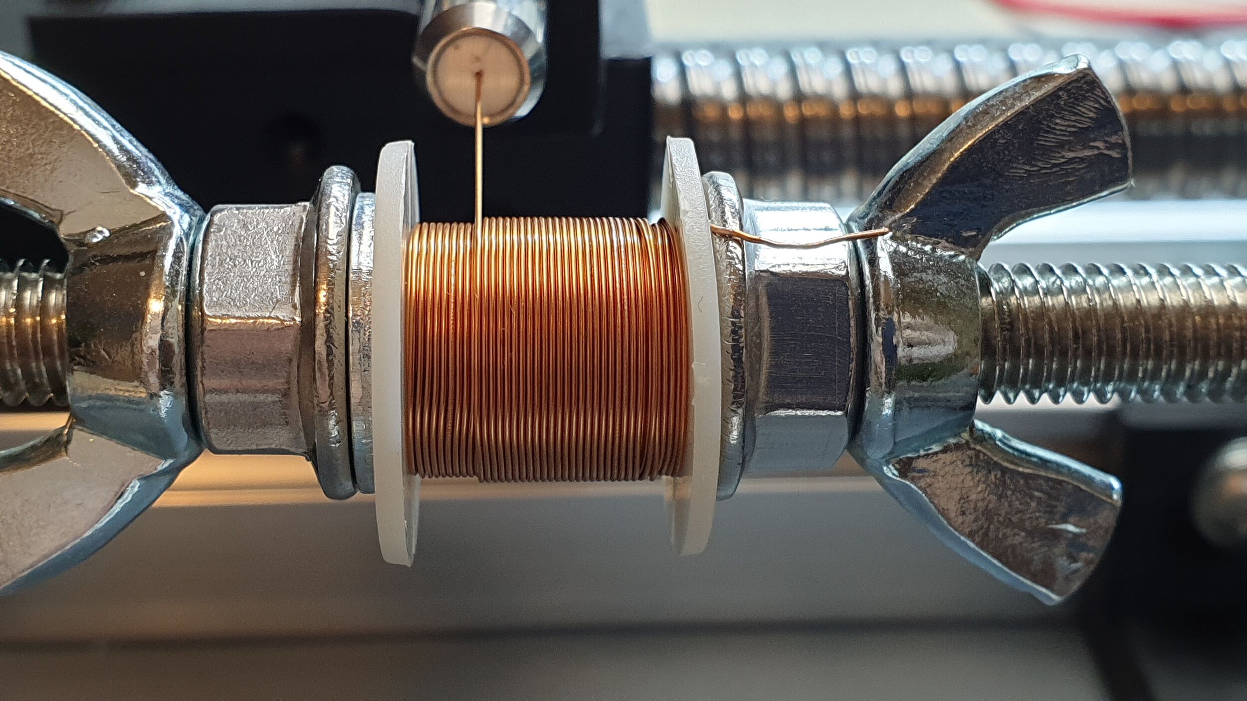
I also made a bit more rigid piece to connect the frame of the main shaft to the rail of the feeder. Furthermore, I designed a mount for the reel holder which allows me to have it attached to the frame of the feeder. So, now, the whole mechanism is a single piece of device.
If you are interested in using my PCB design for your own coil winder, use the links below and let PCBWay to make the boards for you!

As-received PCB, manufactured by PCBWay.

Populated PCB with all the parts soldered in.