TB6600 and Arduino - Wiring and demonstration
In this video I show you how to connect the TB6600 stepper motor controller to an Arduino and a 4-wire stepper motor. With this setup you will be able to control your stepper motor with the AccelStepper library. I talk about the library in detail in the following video video, where I also share the full source code which allows you to have a great control over a stepper motor:
Link to YouTube
Wiring diagram
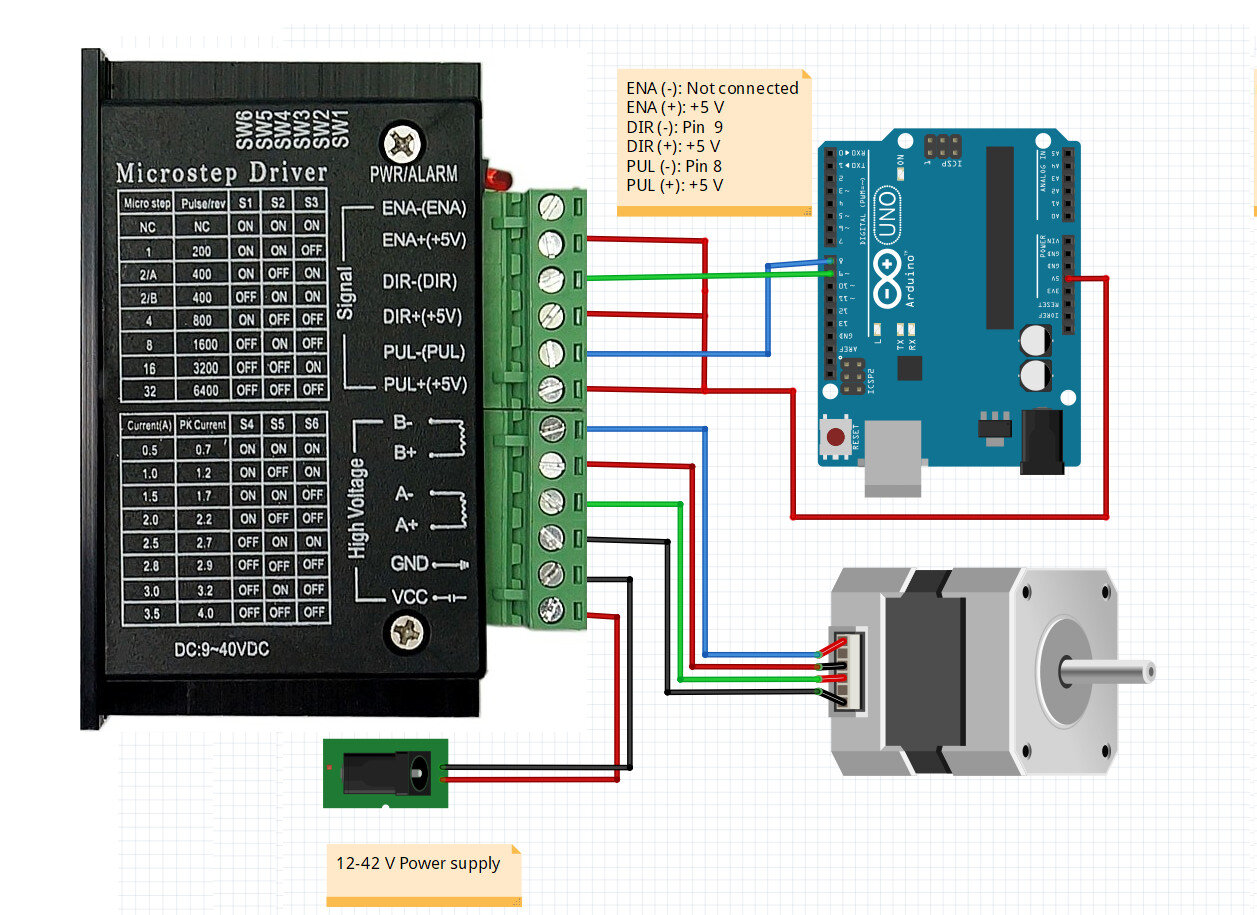
Simplified wiring diagram for the TB6600 stepper motor driver. This is the way I connect the stepper motor to the driver and to the Arduino in all of my videos. The positive signal pins, ENA+, DIR+ and PUL+ are connected to the +5 V rail of the Arduino. The ENA- is not connected, DIR- is the direction pin which is PIN 9 in all my projects, and PUL- is the pulse (or step) pin which is PIN 8 in all my projects. The motor is connected with the same wiring order, however it might happen that your stepper motor’s cables are colored differently. The power supply should be at least 12 V with at least 3 A.