10-channel NTC-based temperature logger
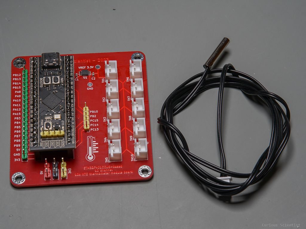
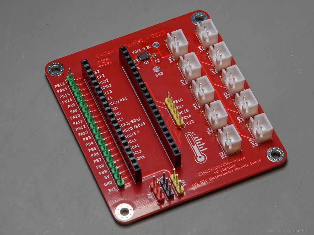
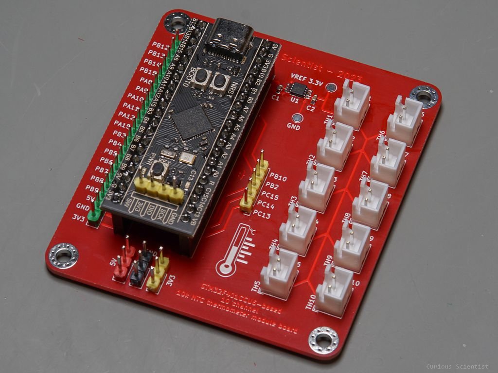
In this project, I show you my most recent device which is a 10-channel temperature logger based on NTC thermometers. I will have some projects where I will need to simultaneously measure temperature at multiple points, so I thought that I should design a dedicated device for it. The project is powered by a STM32F401CCU6 microcontroller board. I picked this board because it has a very powerful microcontroller with 10, 12-bit ADC channels. Since the device has 10 channels, the thermometers occupy all ADCs. But I think it is not a big issue because if we want to additionally measure voltage, we can add an ADS1115 board to it using the i2C communication pins.
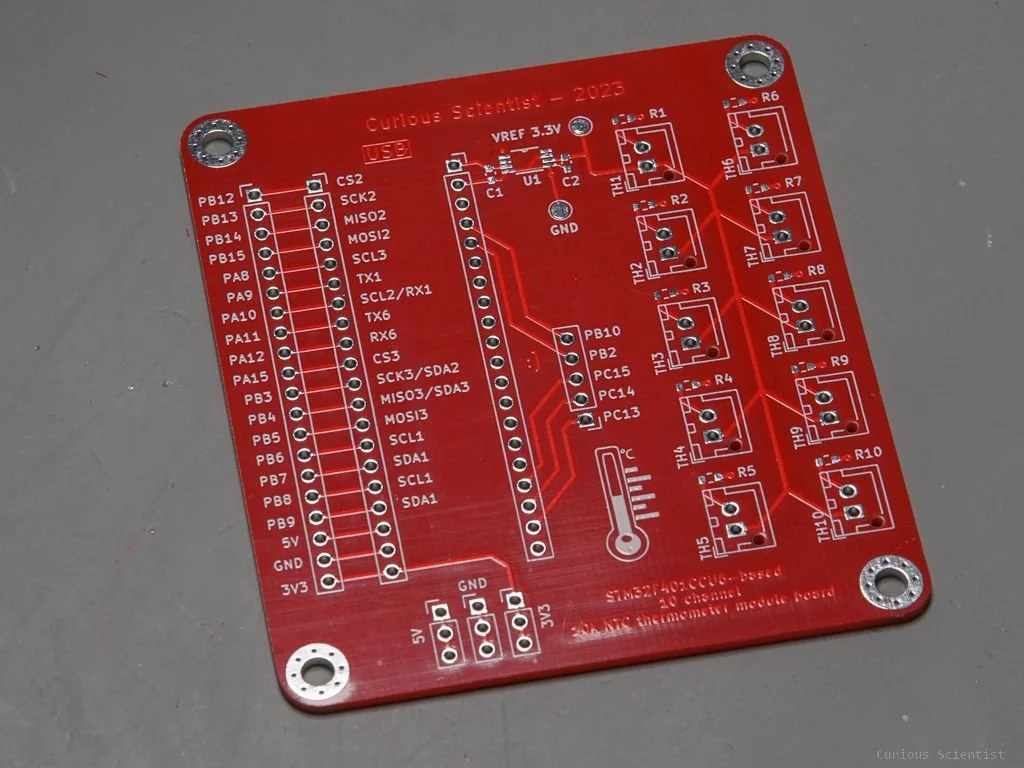
The device is based on 10kOhm NTC thermometers, so the board also has 10k resistors to create the necessary voltage divider for the temperature measurement. The working principles are explained in the section under the video.
The device is also equipped with an SPI-compatible 1.8” TFT LCD. The display simply shows the 10 channels and that’s all.
Working principles of the NTC thermometer
The NTC thermometers are temperature-sensitive resistors. The abbreviation NTC means “negative temperature coefficient” which means that by increasing the temperature of the NTC probe, its resistance will decrease. So, essentially, we have a variable resistor that responds inversely proportional to the temperature (high T = low R, low T = high R).
Of course, we usually do not measure the resistance directly. However, we can put a resistor in series with the thermistor to create a voltage divider. Then we can measure the output voltage of the voltage divider and calculate the temperature based on the parameters of the voltage divider. My circuit realizes this approach. Each of the 10 NTCs has its own 10k 0.1% resistor, and together they create an individual voltage divider. Then the output of each of these 10 voltage dividers is connected to the 10 individual ADC inputs of the STM32F401CCU6 microcontroller. The voltage range of 0 - 3.3 V and the 12-bit resolution of the ADC result in an 806 uV resolution so that we can resolve the temperature change with a sufficient step size.
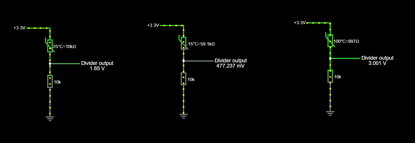
Simple voltage divider in three different cases: 25°C, -15°C and 100°C. At 25°C, the thermistor has 10kOhm resistance, so the output of the voltage divider becomes half of the supply voltage (3.3 V → 1.65 V).

The general formula of the output voltage of a voltage divider with two resistors. The second part of the formula is adjusted to this case where an NTC (R1) is used in series with a 10kOhm resistor (R2) and the supply voltage is set to 3.3 V.
If we want to make a more sophisticated approach, we could build a Wheatstone bridge for each NTC thermistor. But in my opinion, the added complexity (2x10 additional resistors) does not worth the extra effort because this project is aimed at hobby makers (including myself) who are typically OK with +/- 0.5°C accuracy. A Wheatstone bridge would be suitable for measuring very small temperature changes which is outside of the scope of this project.
So, I settled with the simple voltage divider with the thermistor and a 10kOhm resistor in it. At 25°C when the thermistor has 10 kOhm resistance, the expected output voltage of the divider is half the supply voltage.
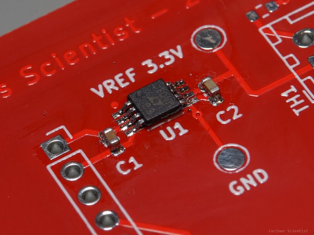
The next step is to find a suitable voltage source. First, I thought I could have a buffered voltage reference in the same way I have for my custom ADS1256 board. But then I did a little calculation and I figured out that I can manage everything with just a voltage reference chip.
When all 10 thermistors are at the maximum possible temperatures (lowest resistance), the total current taken by the 10 voltage dividers is around 3.233 mA. So, all I have to do is to find a voltage reference that can supply such a current. I did not search too much because I also sorted the hits by price, so I quickly found the LTC6652AHMS8-3.3#PBF precision voltage reference. According to its datasheet, it can source or sink 5 mA which is enough for me. It is also a simple chip, it only requires two capacitors and that’s all.
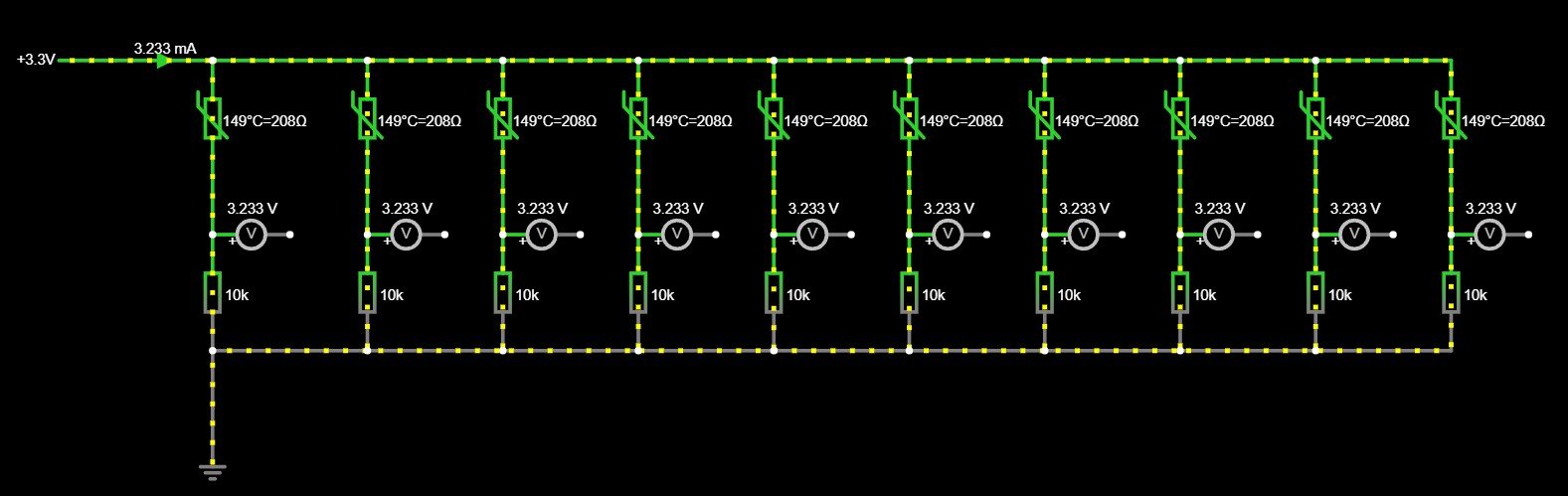
10 thermistors with their 10k resistors supplied by a single 3.3 V source. When the thermistors are at their maximum temperature (lowest resistance) the current drawn by the whole circuit is 3.233 mA.
Get the relevant parts using my affiliate links!
10k NTC thermistor probe - metal capsule
10k NTC thermistor probe - thin
Join my YouTube membership!
Get the PCB from PCBWay!