Precise focus stacking device for macro photography - Part 2
In this video, I show you some updates on my focus stacking rig. After my first video, I kept working on the project because I wanted to improve several things. Both on the software and the hardware side. I designed my own rig based on some off-the-shelf components as well as 3d-printed parts. I also changed a few things in the Arduino code and added some extras to make the program more flexible and user-friendly.
I noticed two spikes in the number of viewers of my previous video on this topic. I found both reasons and I am very happy to see them, so whoever did it, thank you. First, my project was posted on Arduino’s official blog and Facebook page. Then, some days later, someone picked up my project and posted it on Hackaday’s blog. I hope the person sees this article so I can say thank you for posting my work, it really made my day!
I also talked to my friend Allan, who is a great expert in macro photography (and also happens to have a YouTube channel) and we discussed potential improvements to the system.
About the new rig
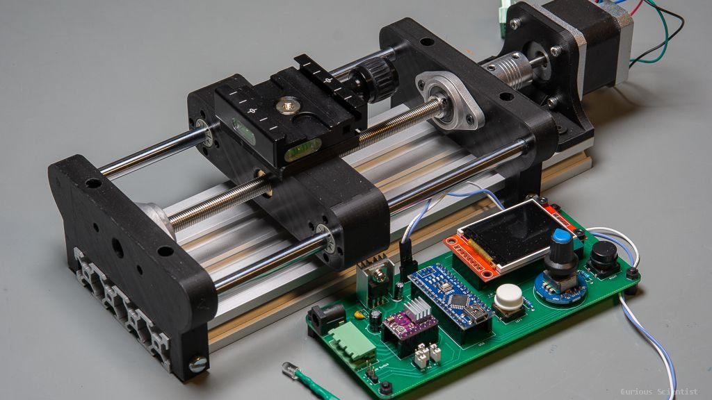
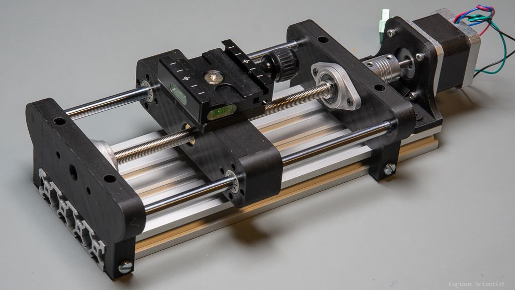
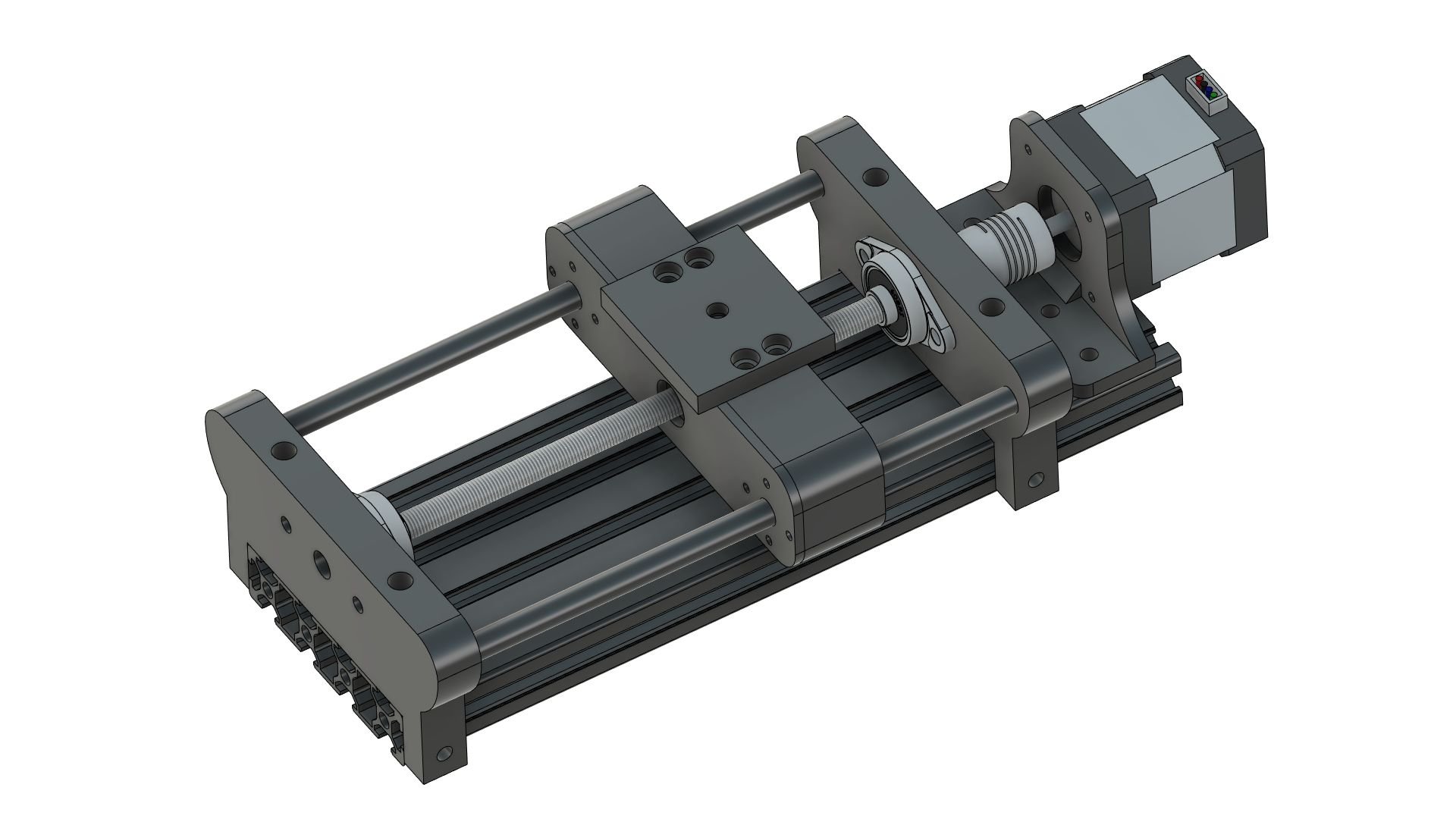
I decided to design my own rig completely from scratch. I wanted to make it robust and wanted to use off-the-shelf components wherever it was possible.
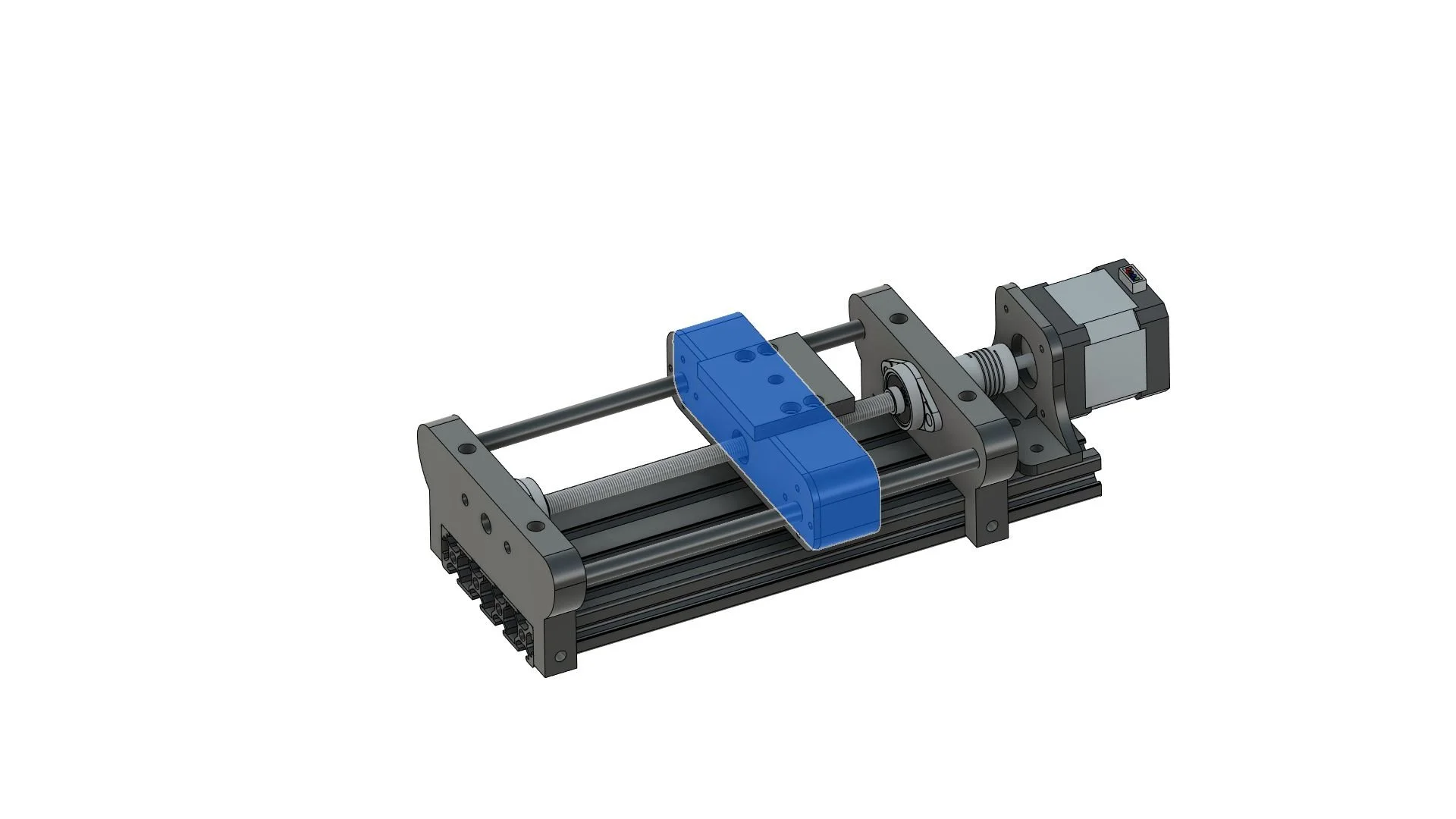
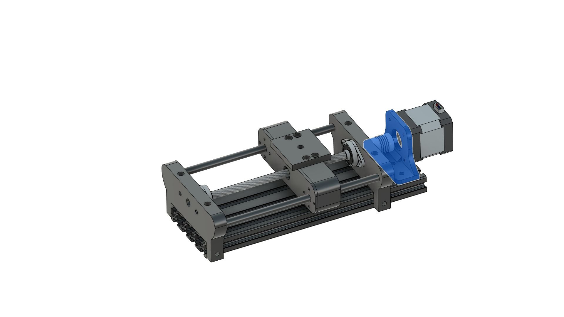
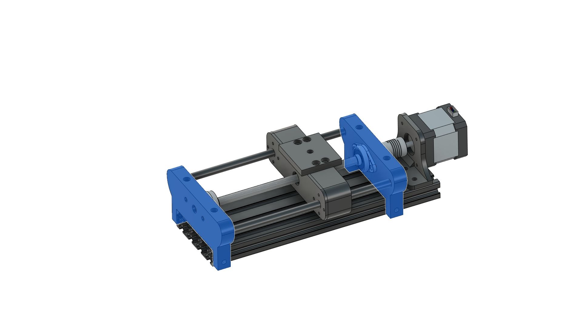
The whole structure is based on a 250 mm long 20x80 aluminium extrusion profile. It is a cheap but stiff mounting surface and thanks to the V-slots it is easy to mount things on it. I picked this length because it is easy to buy off-the-shelf linear rails and lead screws with 200 mm length, so I could use that remaining 50 mm to mount the motor and have some space for the coupler.
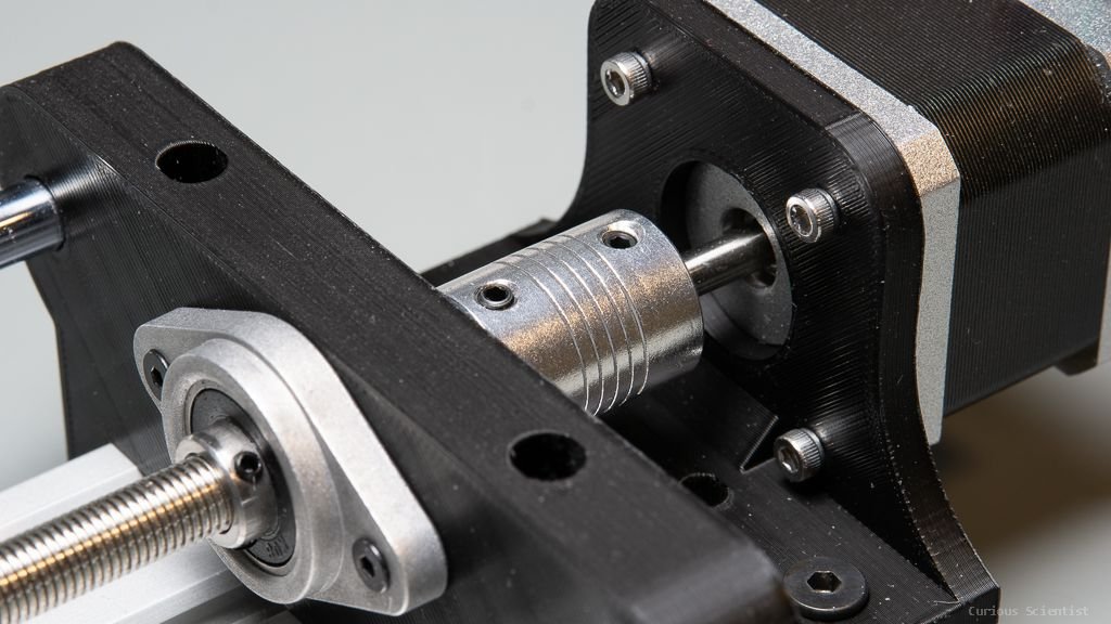
The lead screw is driven by a NEMA17 stepper motor through a coupler. I designed the mounting bracket specifically for this type of motor, but with a new bracket, a NEMA23 could also be mounted if needed. But I think that a beefier version of the NEMA17 (65 Ncm) is perfect enough for this task because everything moves smoothly, so there’s no need for a stronger motor. What I would do is I would use a motor that has 400 steps per turn resolution (0.9° step angle) instead of 200 (1.8° step angle).
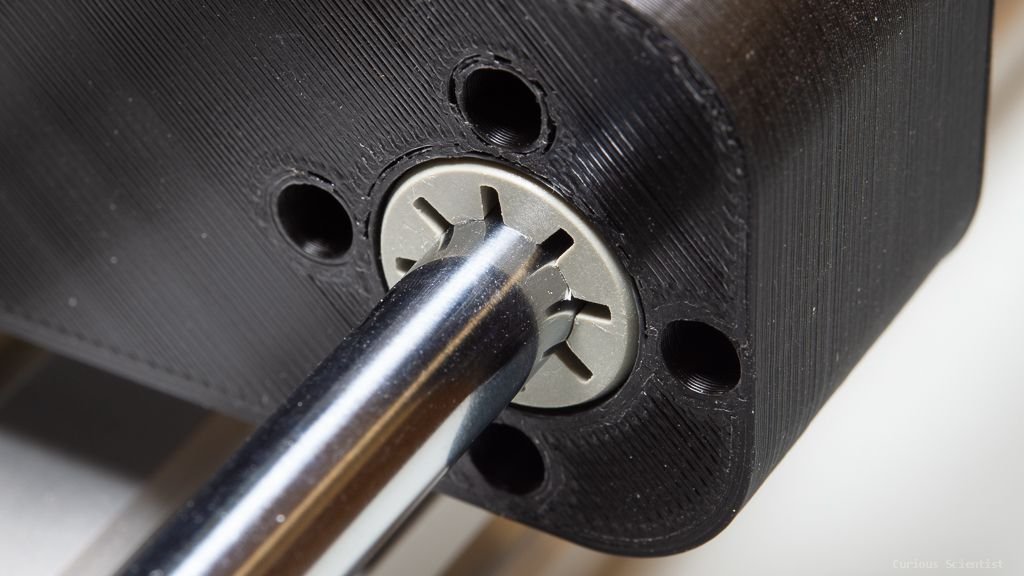
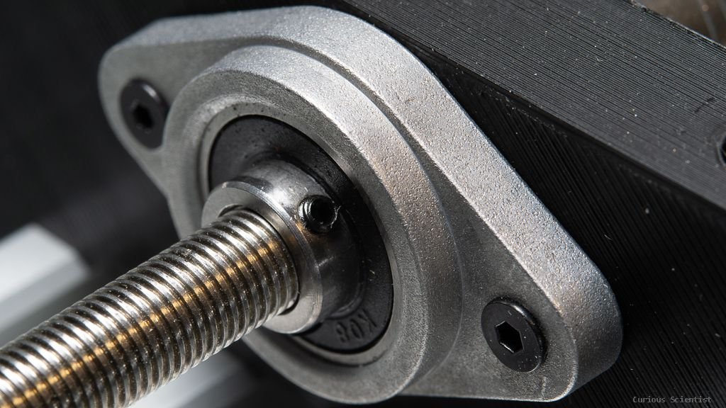
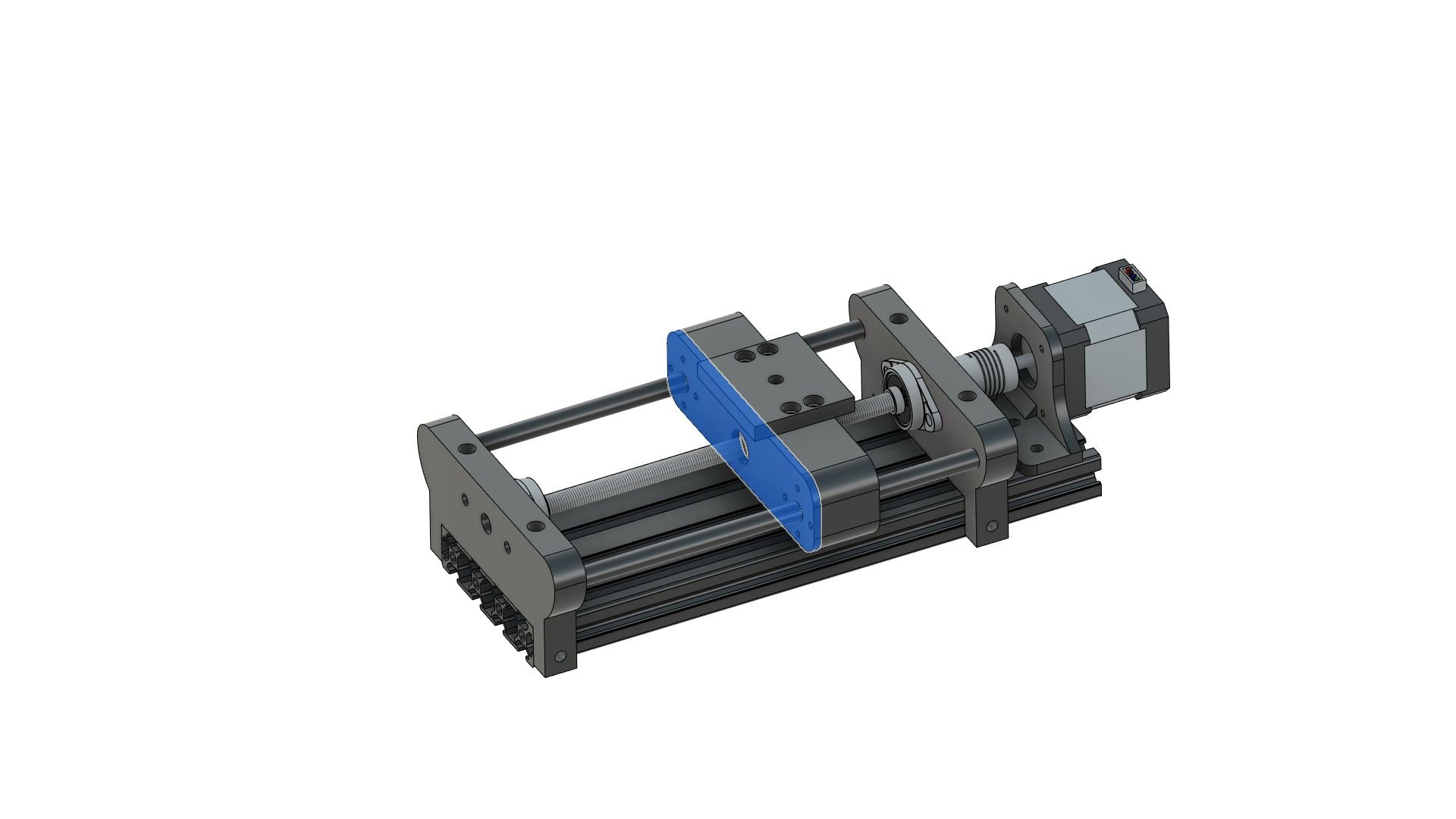
The lead screw is supported by a KFL08 flange bearing on both sides. I used brass insert nuts to fix the bearings, but a bolt through the plastic piece and nut on the other side can also be used. The holes for the bearings go through the whole thickness of the holder. The lead screw I used has a 1 mm pitch which means that a full turn results in a 1 mm linear displacement. So even without microstepping, the theoretical step size of the system is 5 um. If you crank up the microstepping to have 1600 steps per turn, you could theoretically have a 625 nm step size. But due to the compliance and all other mechanical things, I don’t think that the system would be able to step with such a small step size consistently. Also, I don’t have the instruments to measure such small displacements. The lead screw is also equipped with an anti-backlash spring-loaded nut.
There is an 8 mm linear rail on each side of the lead screw. They support the crosshead and allow smooth movement and they also distribute the load coming from the camera mounted on the crosshead. I used Igus Drylin linear bearings for this project.
A few words about the software
There are many options that the user can adjust, so let’s go through them one by one:
f/N: Aperture - This is self-explanatory, it is the aperture you set for the system
Magnification: Also self-explanatory. If you have a macro lens, then it is written on the lens
DOF: Depth of field based on the entered aperture and magnification values
Stp: Step size. This is the distance between two steps on the linear rail. The default value is DOF/2, but if you change it manually, the software will use your values. However, if you change the aperture or magnification again, then the setting reverts to the default DOF/2 until you change the step size again manually.
Finish point: This is where the stacking is finished. This point has to be the farthest sharp area on your subject*. Look at your camera’s live view image and navigate the rig until you reach the farthest point. I recommend overshooting this point a little bit, so after the far end of your subject became sharp, keep going in the same direction by a few step size distance. This is just a safety measure to compensate for the backlash. Unit is defined in millimetres.
Start point: This is where the stacking starts. This is the subject’s closest point to your lens*. Ideally, you set this value after you set the finish point (that’s why the finish point comes first on the display), so now you have to navigate backwards until the “tip” of your subject becomes sharp. I recommend overshooting this point a little bit, so after the “tip” became sharp, keep going in the same direction by a few step size distance. This is just a safety measure to compensate for the backlash. Unit is defined in millimetres.
Travel distance: It is automatically calculated based on the distance between the start and finish points. Unit is defined in millimetres.
Number of steps: It is simply the travel distance divided by the step size. The value is an integer value, so it can occur that there is a ±1 step discrepancy between the calculated value and the real number of steps done due to rounding.
Progress: It is the number of the actual frame.
GO!: It starts the stacking after the right button is pressed. The stacking can be interrupted by long pressing (>3-5 seconds) of the left button.
Homing: It runs the motor towards the limit switch and when the limit switch is reached, it parks the motor. By default, the switch should be placed somewhere between the motor and the crosshead.
Microstepping: You can select the set microstepping value between 200 and 6400. (Tailored for DRV8825)
Screw pitch: It is the pitch of the lead screw. Pitch is also the linear travel of the nut per screw turn.
Step length: The linear travel caused by a single step based on the microstepping and screw pitch.
Dwell time: Waiting time between two steps in seconds. The dwell time is split up into two parts. Half of the dwell time is the waiting time after the motor did a step. This is to let the vibrations settle. The other half is the waiting time after we send out the shutter signal via the IR LED. The camera does not react immediately after receiving the IR signal, so we cannot start moving to the next step right away after sending out the IR signal, otherwise, the image won’t be sharp.
*: This might depend on the polarity of the stepper, so it is better to check it manually first if the motor moves from start→finish or finish→start.

First page. Values in the cyan-coloured frames can be changed by the user. The values in the green frames are calculated by the software.

Second. page. Values in the cyan-coloured frames can be changed by the user. The values in the green frames are calculated by the software.
3D files, Arduino software and other things

I put all the 3D files in a zip file that you can download directly. The parts should have a snug fit, maybe even a little filing or hot air will be needed to for the final adjustments. I adjusted the diameters for the tolerances of my printer (Ender 3 MAX), so it can happen that your printer might print differently and you would have a different experience regarding the fit of the parts. I don’t take any responsibility for the fit and the tolerances of the 3D models.

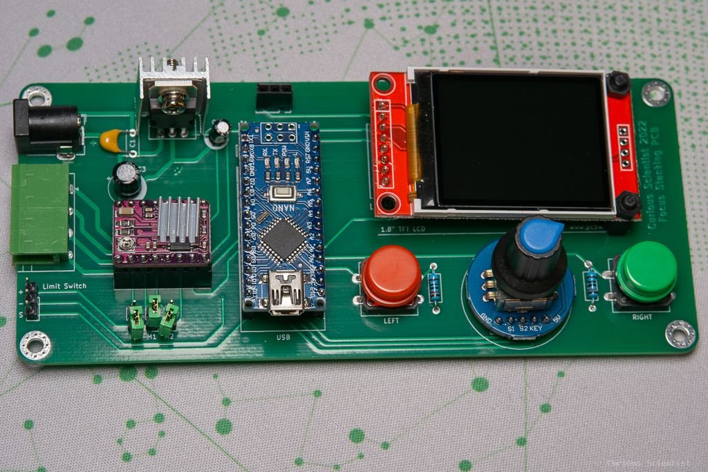
The PCB is available on my project page on PCBWay’s website. If you purchase the board from them, you also support my work by a small amount.
The Arduino source code is available for my YouTube membership supporters!
Relevant parts and components
Purchase the components using my affiliate links!
1 mm pitch lead screw with anti-backlash nut