Positioning with the N20 miniature geared DC motors
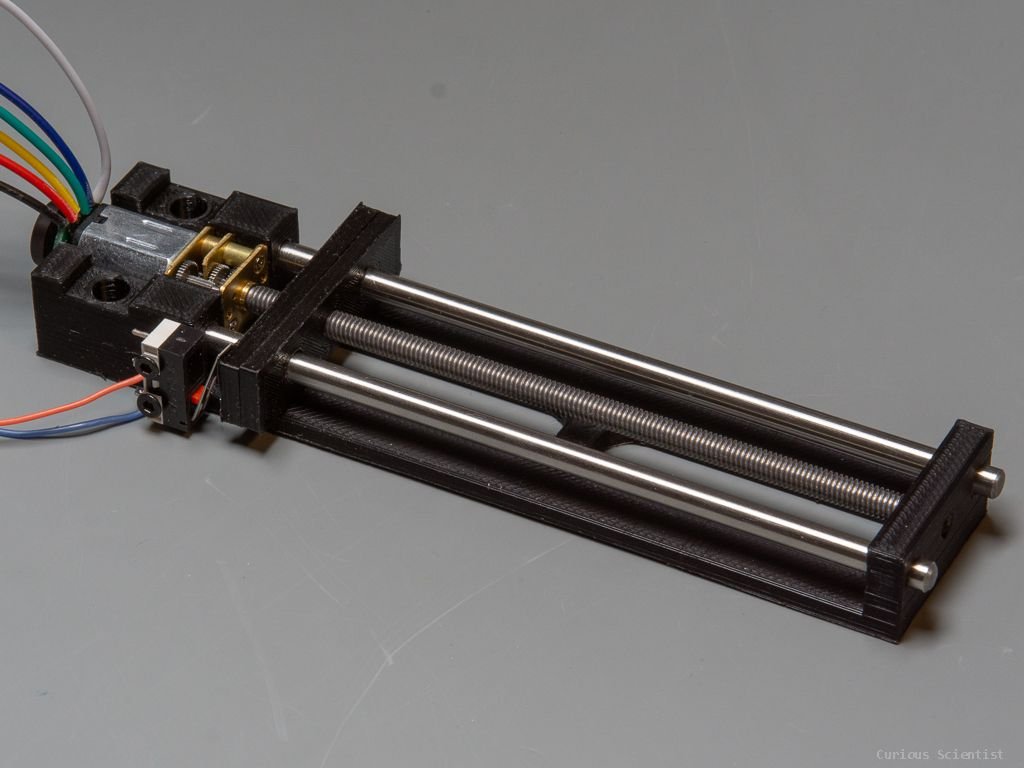
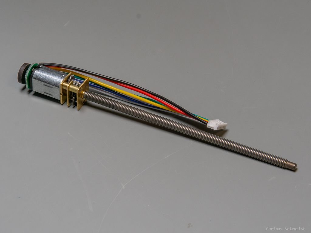
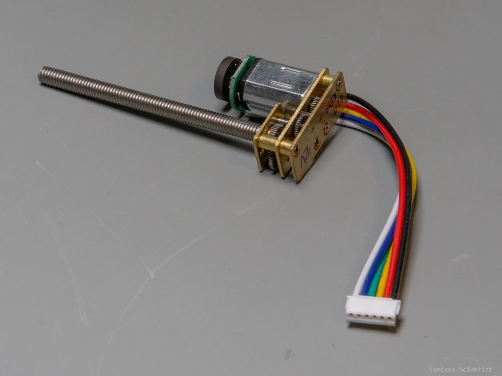
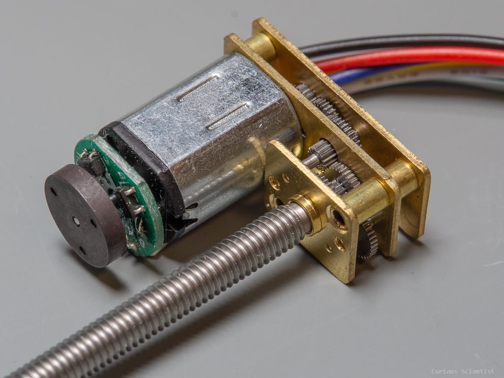
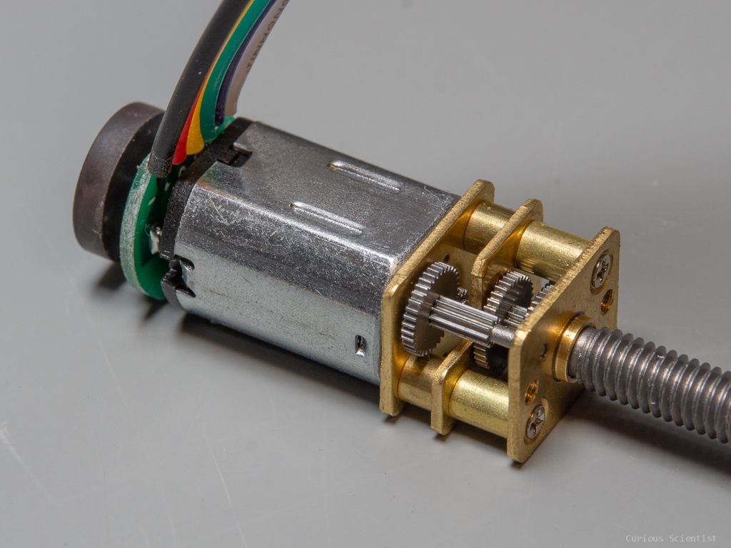
In this video I show you how to set up a system to drive the N20 geared DC motors with a simple PID algorithm. These motors are good for many applications because they are lightweight, relatively precise, and based on the selected gearbox, they can be either fast or produce “high” torque. Typically, their speed can vary from anything between 30 RPM up to 600 RPM depending on the gearbox configuration. The motors typically have 3 PPR (pulses per revolution) encoders, but with careful searching, one can find motors with higher resolution encoders. The mechanism is usually equipped with an M4 threaded shaft (0.7 mm pitch), but sometimes they come with M3 threaded shaft, or even with a M4 lead screw (trapezoidal threads). They can be used for positioning with a relatively good accuracy and repeatability. I created a 3d-printable carriage for the 55 mm and 100 mm versions so you can use the motor for linear positioning.
Extra resources
You can find the relevant parts using my Aliexpress affiliate links:
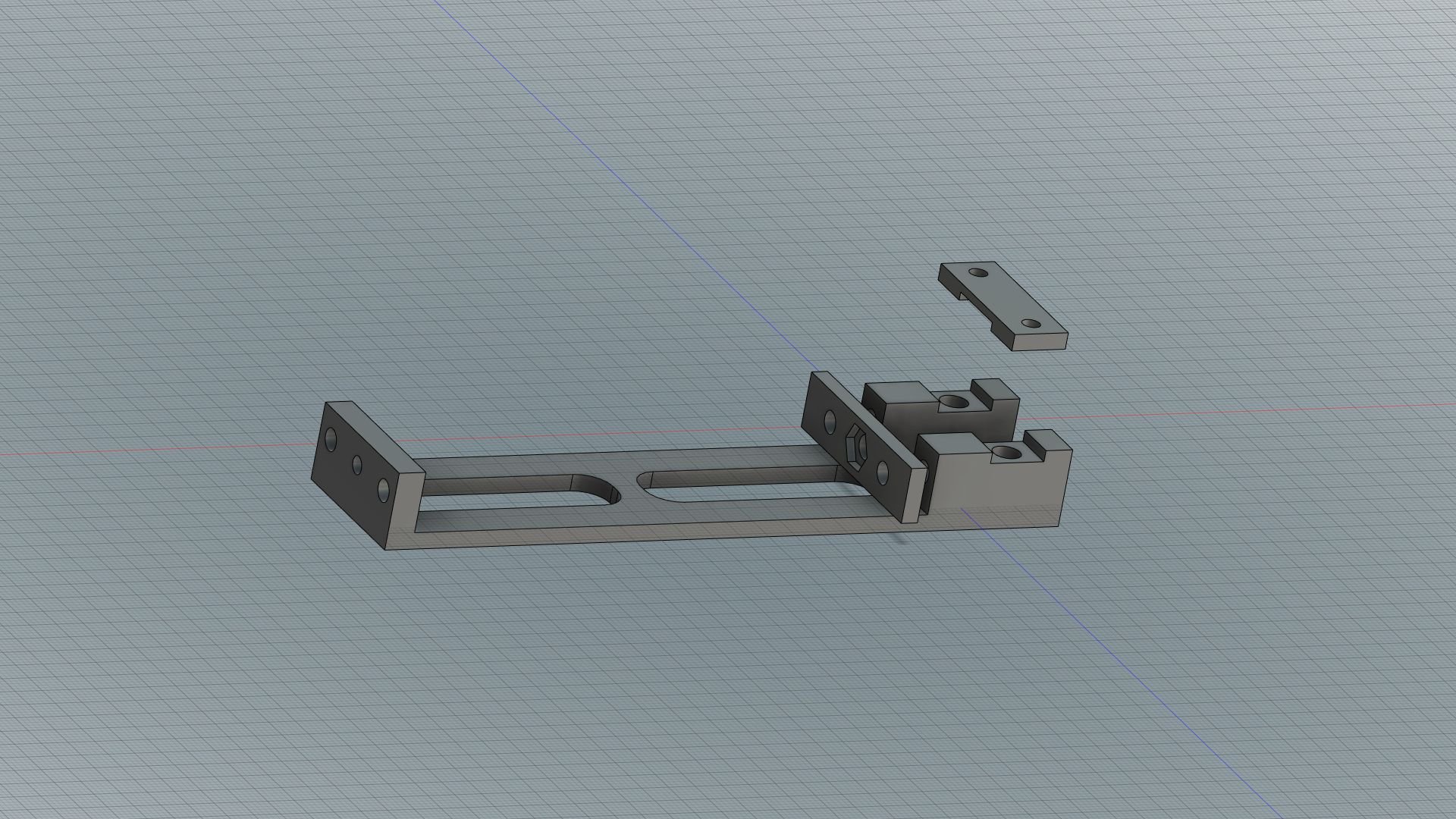
Some remarks about the 3d-printable models:
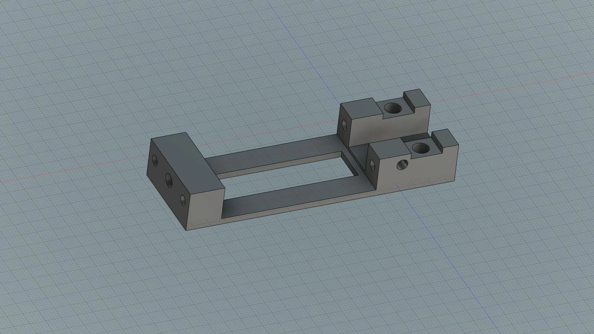
I made the models to have a little snug fit because it is always easier to drill and file a little bit than to add material if something is too loose.
The support rails I used are 4 mm steel rods. They are typical “hobby accessories”, so it is easy to buy them.
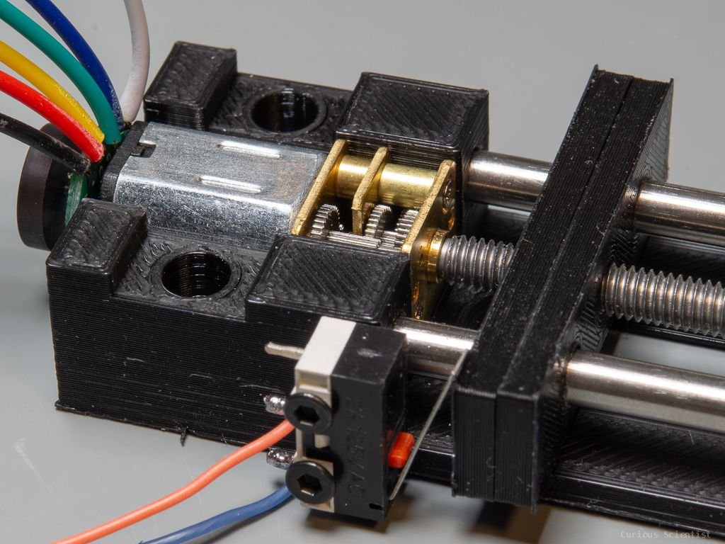
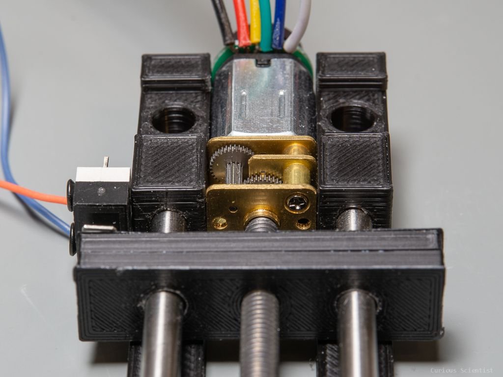
The two holes on the sides of the area where the motor sits are made for insert nuts. However, the frame is tight enough to hold the motor without extra clamping.
The crosshead is made of 2 identical pieces. You need to print 2 crosshead pieces, then sandwich a regular M4 nut in the middle and glue the two parts together. Align it carefully.
The limit switch is supported by 2 M2 bolts. The limit switch can be an Omron D2F5L switch.
Schematics

The wiring is the same as I used in the video for the demonstration. All the pin connections are the same as in the source code. Make sure that you have a sufficient power supply for the motor driver. Don’t drive the motor from the 5 V pin of the Arduino, use an external power source as I did. For the rotary encoder, it is probably good enough to use the INPUT_PULLUP in the Arduino for pull-up resistors, but just to be sure, I added normal resistors as pull-up resistors for the motor’s encoder pins. Depending on which motor you use, it can happen that the motor behaves the opposite way. Just “mirror” the pins (A1 becomes A2 and A2 becomes A1…etc) or flip everything in the code.