Measuring speed and position using the AS5600
In this video I show you some nice features that I developed for the AS5600 magnetic position encoder. Using my custom made PCB and a NEMA17 motor I show you how accurate the stepper motor is. I tried to determine the speed and the position of the stepper motor's shaft using the AS5600. I also compared the position and speed values with the values provided by the AccelStepper library. According to the experiment, the position is followed exactly, without skipping even a single step. On the other hand, I have some small issues with the speed which is probably due to some programming mistake that I could not notice.
Schematics

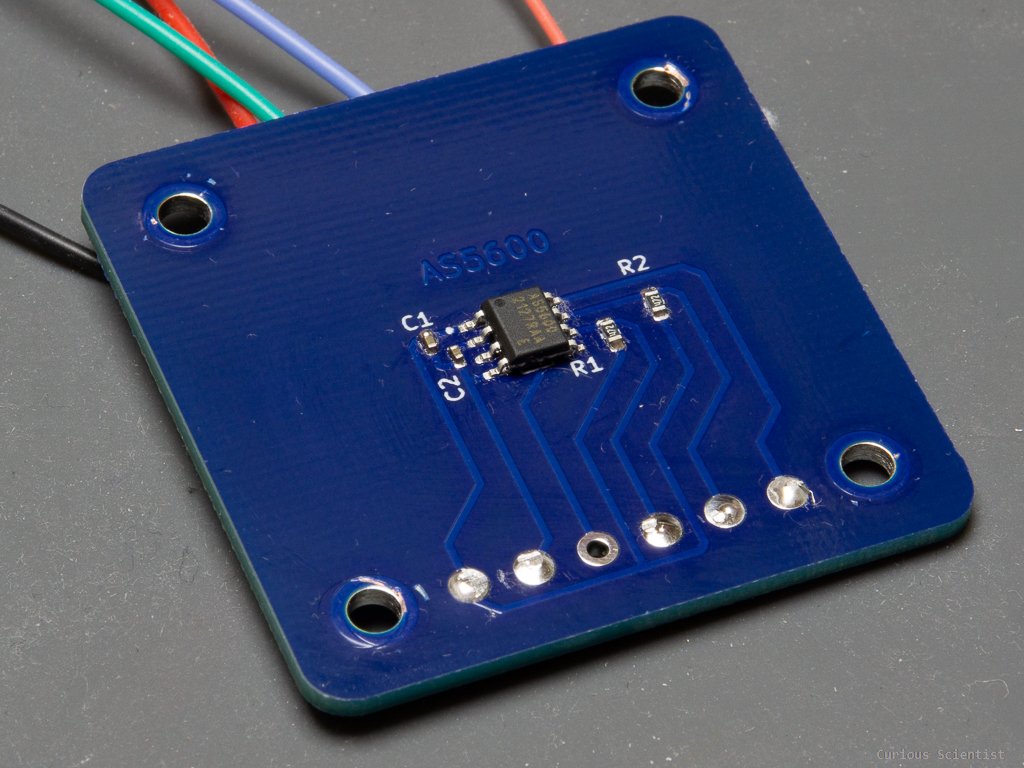
Schematics of the circuit used for the demo. Please forgive the ugly way of including the AS5600 board. Since it is a simple i2c board, the connection is really straightforward. Also, make sure that you connect the DIR pin to ground if you don’t use it.
Arduino source code
#include "TimerOne.h" //Timer interrupts
#include <Wire.h> //This is for i2C
#include <SSD1306Ascii.h> //i2C OLED
#include <SSD1306AsciiWire.h> //i2C OLED

// i2C OLED
#define I2C_ADDRESS 0x3C
#define RST_PIN -1
SSD1306AsciiWire oled;
float OLEDTimer = 0; //Timer for the screen refresh
//I2C pins:
//STM32: SDA: PB7 SCL: PB6
//Arduino: SDA: A4 SCL: A5
//---------------------------------------------------------------------------
#include <AccelStepper.h>
AccelStepper stepper(1, 10, 11);// pulses/steps 10; Direction 11
volatile float stepperMotorSpeed = 0;
//---------------------------------------------------------------------------
//Input and output pins
const int RotaryCLK = 3; //CLK pin on the rotary encoder, interrupt pin!
const int RotaryDT = 4; //DT pin on the rotary encoder, read inside the interrupt
const int RotarySW = 5; //SW pin on the rotary encoder (Button function)
bool rotaryRotated = false;
int RotaryButtonValue = 0; //0 or 1 (pressed or not)
float RotaryTime; //timer for debouncing
volatile int rotaryValue = 0; //value manipulated by the encoder
int previousRotaryValue = -1; //a variable which stores the previous value - easy to follow changes
int CLKNow;
int CLKPrevious;
int DTNow;
int DTPrevious;
//---------------------------------------------------------------------------
//Magnetic sensor things
int magnetStatus = 0; //value of the status register (MD, ML, MH)

int lowbyte; //raw angle 7:0
word highbyte; //raw angle 7:0 and 11:8
int rawAngle; //final raw angle
float degAngle; //raw angle in degrees (360/4096 * [value between 0-4095])

int quadrantNumber, previousquadrantNumber; //quadrant IDs
float numberofTurns = 0; //number of turns
float correctedAngle = 0; //tared angle - based on the startup value
float startAngle = 0; //starting angle
float totalAngle = 0; //total absolute angular displacement
float previoustotalAngle = -1; //for the display printing
float recentTotalAngle = 0; //for the display printing
float rpmValue = 0; //revolutions per minute
float stepRateFromRPM = 0; //steps/s calculated from RPM
float calculatedRPM = 0; //calculated RPM based on the stepper speed
float stepperPosition = 0; //stepper's software position based on the AccelStepper library
float stepperPreviousPosition = 0; //stepper's software position based on the AccelStepper library
float rpmInterval = 200; // RPM is calculated every 0.2 seconds
float rpmTimer = 0; //Timer for the rpm
float timerdiff = 0; //Time difference for more exact rpm calculation

void setup()
{
  //This uses the timer1 of the Arduino
  Timer1.initialize(100); //100 us timer trigger interval
  Timer1.setPeriod(100);
  Timer1.attachInterrupt(callback);  // attaches callback() as a timer overflow interrupt
  //The timer interval has to be adjusted according to the maximum expected motor speed!
  //------------------------------------------------------------------------------

  Serial.begin(115200); //start serial - tip: don't use serial if you don't need it (speed considerations)
  Wire.begin(); //start i2C
  Wire.setClock(800000L); //fast clock

  checkMagnetPresence(); //check the magnet (blocks until magnet is found)

  ReadRawAngle(); //make a reading so the degAngle gets updated
  startAngle = degAngle; //update startAngle with degAngle - for taring

  //------------------------------------------------------------------------------
  //OLED part
#if RST_PIN >= 0
  oled.begin(&Adafruit128x32, I2C_ADDRESS, RST_PIN);
#else // RST_PIN >= 0
  oled.begin(&Adafruit128x32, I2C_ADDRESS);
#endif // RST_PIN >= 0

  //Definition of the pins, remember where you need
  pinMode(RotaryCLK, INPUT_PULLUP); //CLK
  pinMode(RotaryDT, INPUT_PULLUP); //DT
  pinMode(RotarySW, INPUT_PULLUP); //SW
  attachInterrupt(digitalPinToInterrupt(RotaryCLK), RotaryEncoder, CHANGE);
  //Store states
  CLKPrevious = digitalRead(RotaryCLK);
  DTPrevious = digitalRead(RotaryDT);
  //------------------------------------------------------------------------------

  oled.setFont(Adafruit5x7);
  oled.clear(); //clear display
  oled.set2X(); //double-line font size - better to read it
  oled.println(" Welcome!"); //print a welcome message
  oled.println("  AS5600"); //print a welcome message
  oled.set1X(); //double-line font size - better to read it
  delay(1000);
  OLEDTimer = millis(); //start the timer
  oled.clear();
  refreshDisplay();
  //Stepper setup---------------------------------------------------------
  stepper.setSpeed(0); //SPEED = Steps / second
  stepper.setMaxSpeed(10000); //SPEED = Steps / second
  stepper.setAcceleration(5000); //ACCELERATION = Steps /(second)^2

}

void callback()
{
  stepper.runSpeed();
}

void loop()
{
  ReadRawAngle(); //ask the value from the sensor
  correctAngle(); //tare the value
  checkQuadrant(); //check quadrant, check rotations, check absolute angular position
  calculateRPM(); //Calculate RPM
  CheckRotaryButton(); //Check (poll) the button on the rotary encoder
  refreshDisplay(); //Update the OLED if values were changed (TIME CONSUMING!)

  stepper.setSpeed(stepperMotorSpeed);
}

void ReadRawAngle()
{
  //7:0 - bits
  Wire.beginTransmission(0x36); //connect to the sensor
  Wire.write(0x0D); //figure 21 - register map: Raw angle (7:0)
  Wire.endTransmission(); //end transmission
  Wire.requestFrom(0x36, 1); //request from the sensor

  while (Wire.available() == 0); //wait until it becomes available
  lowbyte = Wire.read(); //Reading the data after the request

  //11:8 - 4 bits
  Wire.beginTransmission(0x36);
  Wire.write(0x0C); //figure 21 - register map: Raw angle (11:8)
  Wire.endTransmission();
  Wire.requestFrom(0x36, 1);

  while (Wire.available() == 0);
  highbyte = Wire.read();

  //4 bits have to be shifted to its proper place as we want to build a 12-bit number
  highbyte = highbyte << 8; //shifting to left
  //What is happening here is the following: The variable is being shifted by 8 bits to the left:
  //Initial value: 00000000|00001111 (word = 16 bits or 2 bytes)
  //Left shifting by eight bits: 00001111|00000000 so, the high byte is filled in

  //Finally, we combine (bitwise OR) the two numbers:
  //High: 00001111|00000000
  //Low:  00000000|00001111
  //      -----------------
  //H|L:  00001111|00001111
  rawAngle = highbyte | lowbyte; //int is 16 bits (as well as the word)

  //We need to calculate the angle:
  //12 bit -> 4096 different levels: 360° is divided into 4096 equal parts:
  //360/4096 = 0.087890625
  //Multiply the output of the encoder with 0.087890625
  degAngle = rawAngle * 0.087890625;

  //Serial.print("Deg angle: ");
  //Serial.println(degAngle, 2); //absolute position of the encoder within the 0-360 circle

}

void correctAngle()
{
  //recalculate angle
  correctedAngle = degAngle - startAngle; //this tares the position

  if (correctedAngle < 0) //if the calculated angle is negative, we need to "normalize" it
  {
    correctedAngle = correctedAngle + 360; //correction for negative numbers (i.e. -15 becomes +345)
  }
  else
  {
    //do nothing
  }
  //Serial.print("Corrected angle: ");
  //Serial.println(correctedAngle, 2); //print the corrected/tared angle
}

void checkQuadrant()
{
  /*
    //Quadrants:
    4  |  1
    ---|---
    3  |  2
  */

  //Quadrant 1
  if (correctedAngle >= 0 && correctedAngle <= 90)
  {
    quadrantNumber = 1;
  }

  //Quadrant 2
  if (correctedAngle > 90 && correctedAngle <= 180)
  {
    quadrantNumber = 2;
  }

  //Quadrant 3
  if (correctedAngle > 180 && correctedAngle <= 270)
  {
    quadrantNumber = 3;
  }

  //Quadrant 4
  if (correctedAngle > 270 && correctedAngle < 360)
  {
    quadrantNumber = 4;
  }
  //Serial.print("Quadrant: ");
  //Serial.println(quadrantNumber); //print our position "quadrant-wise"

  if (quadrantNumber != previousquadrantNumber) //if we changed quadrant
  {
    if (quadrantNumber == 1 && previousquadrantNumber == 4)
    {
      numberofTurns++; // 4 --> 1 transition: CW rotation
    }

    if (quadrantNumber == 4 && previousquadrantNumber == 1)
    {
      numberofTurns--; // 1 --> 4 transition: CCW rotation
    }
    //this could be done between every quadrants so one can count every 1/4th of transition

    previousquadrantNumber = quadrantNumber;  //update to the current quadrant

  }
  //Serial.print("Turns: ");
  //Serial.println(numberofTurns,0); //number of turns in absolute terms (can be negative which indicates CCW turns)

  //after we have the corrected angle and the turns, we can calculate the total absolute position
  totalAngle = (numberofTurns * 360) + correctedAngle; //number of turns (+/-) plus the actual angle within the 0-360 range
  //Serial.print("Total angle: ");
  //Serial.println(totalAngle, 2); //absolute position of the motor expressed in degree angles, 2 digits
}

void checkMagnetPresence()
{
  //This function runs in the setup() and it locks the MCU until the magnet is not positioned properly

  while ((magnetStatus & 32) != 32) //while the magnet is not adjusted to the proper distance - 32: MD = 1
  {
    magnetStatus = 0; //reset reading

    Wire.beginTransmission(0x36); //connect to the sensor
    Wire.write(0x0B); //figure 21 - register map: Status: MD ML MH
    Wire.endTransmission(); //end transmission
    Wire.requestFrom(0x36, 1); //request from the sensor

    while (Wire.available() == 0); //wait until it becomes available
    magnetStatus = Wire.read(); //Reading the data after the request

    //Serial.print("Magnet status: ");
    //Serial.println(magnetStatus, BIN); //print it in binary so you can compare it to the table (fig 21)
  }

  //Status register output: 0 0 MD ML MH 0 0 0
  //MH: Too strong magnet - 100111 - DEC: 39
  //ML: Too weak magnet - 10111 - DEC: 23
  //MD: OK magnet - 110111 - DEC: 55

  //Serial.println("Magnet found!");
  //delay(1000);
}

void calculateRPM()
{
  //This function calculates the RPM based on the elapsed time and the angle of rotation.
  //Positive RPM is CW, negative RPM is CCW. Example: RPM = 300 - CW 300 rpm, RPM = -300 - CCW 300 rpm.
  timerdiff = millis() - rpmTimer;

  if (timerdiff > rpmInterval)
  {

    //rpmValue = (60000.0/rpmInterval) * (totalAngle - recentTotalAngle)/360.0;
    rpmValue = (60000.0 / timerdiff) * (totalAngle - recentTotalAngle) / 360.0;
    //Formula: (60000/2000) * (3600 - 0) / 360;
    //30 * 10 = 300 RPM. So, in 2 seconds we did 10 turns (3600degrees total angle), then assuming that the speed is constant
    //2 second is 1/30th of a minute, so we multiply the 2 second data with 30 -> 30*10 = 300 rpm.
    //The purpose of the (60000/rpmInterval) is that we always normalize the rounds per rpmInterval to rounds per minute

    //Step rate (steps/s) is assumed with 800 steps/360° microstepping. 1 step = 0.45°
    //1 RPM = 800 steps/minute because of the 800 steps/revolution microstepping
    //We also divide by 60, because we want the units to be in steps/s
    stepRateFromRPM = rpmValue * 800.0 / 60.0;

    //Also, keep in mind that 800 steps/s means that every 1.25 ms (1250 us) we need to do a step.
    //The maximum desired speed has to be kept in mind when you define the interrupt frequency.

    recentTotalAngle = totalAngle; //Make the totalAngle as the recent total angle.
    rpmTimer = millis(); //Update the timer with the current millis() value
  }
}

void refreshDisplay()
{
  //Display layout

  // Accelstepper   AS5600
  //-----------------------------
  // Steps/s        CALCULATED
  // CALCULATED     RPM
  // POSITION       CALCULATED
  // CALCULATED     TOTALANGLE

  if (millis() - OLEDTimer > 10) //chech if we will update at every 10 ms
  {
    stepperPosition = stepper.currentPosition();
    if (totalAngle != previoustotalAngle || rotaryRotated == true || stepperPreviousPosition != stepperPosition) //if there's a change in the position*
    {

      //LINE 1 - STEPS/S
      //Accelstepper speed (steps/s)
      oled.setCursor(0, 0);
      oled.print("        ");
      oled.setCursor(0, 0);
      oled.print(stepperMotorSpeed, 1); //ACCELSTEPPER

      oled.setCursor(70, 0);
      oled.print("        ");
      oled.setCursor(70, 0);
      oled.print(-1.0 * stepRateFromRPM, 1); //Calculated from AS5600
      //-----------------------------------------------
      //LINE 2 - RPM
      //Accelstepper RPM
      oled.setCursor(0, 1);
      oled.print("        ");
      oled.setCursor(0, 1);
      oled.print(calculatedRPM, 1); //Calculated from ACCELSTEPPER

      oled.setCursor(70, 1);
      oled.print("        ");
      oled.setCursor(70, 1);
      oled.print(-1.0 * rpmValue, 1); //Measured by AS5600
      //--------------------------------------------------------------------
      //LINE 3 - POSITION
      oled.setCursor(0, 2);
      oled.print("        ");
      oled.setCursor(0, 2);
      oled.print(stepperPosition, 0); //ACCELSTEPPER Position

      oled.setCursor(70, 2);
      oled.print("        ");
      oled.setCursor(70, 2);
      oled.print(-1 * totalAngle / 0.45, 0); //Calculated position from AS5600 total angle
      //--------------------------------------------------------------------
      //LINE 4 - ANGLE
      oled.setCursor(0, 3);
      oled.print("        ");
      oled.setCursor(0, 3);
      oled.print(stepperPosition * 0.45, 2);

      oled.setCursor(70, 3);
      oled.print("        ");
      oled.setCursor(70, 3);
      oled.print(-1 * totalAngle, 2);
      //--------------------------------------------------------------------

      rotaryRotated = false;
      OLEDTimer = millis(); //reset timer
      stepperPreviousPosition = stepperPosition;
      previoustotalAngle = totalAngle; //update the previous value
    }
    //If the code enters this part, it takes about 40-50 ms to update the display
    //800 steps/s = 60 rpm = 360°/s -> 90° degree is 250 ms. (Why 90°? -> quadrants!)
    //So, this code is reliable up to 240 RPM without any "optimization".
  }
  else
  {
    //skip
  }
  //*idea: you can define a certain tolerance for the angle so the screen will not flicker
  //when there is a 0.08 change in the angle (sometimes the sensor reads uncertain values)
}

void RotaryEncoder()
{
  CLKNow = digitalRead(RotaryCLK); //Read the state of the CLK pin
  // If last and current state of CLK are different, then a pulse occurred
  if (CLKNow != CLKPrevious  && CLKNow == 1)
  {
    if (digitalRead(RotaryDT) != CLKNow) //the increment/decrement can depend on the actual polarity of CLK and DT
    {
      stepperMotorSpeed = stepperMotorSpeed - 10;
    }
    else
    {
      stepperMotorSpeed = stepperMotorSpeed + 10;
    }
    calculatedRPM = stepperMotorSpeed * 60.0 / 800.0;
    rotaryRotated = true;
  }
  CLKPrevious = CLKNow;  // Store last CLK state
}

void CheckRotaryButton()
{
  RotaryButtonValue = digitalRead(RotarySW); //read the button state

  if (RotaryButtonValue == 0) //0 and 1 can differ based on the wiring
  {
    if (millis() - RotaryTime > 1000)
    {
      //Reset everything AccelStepper-related
      stepperPosition = 0;
      stepper.setCurrentPosition(0);
      stepperMotorSpeed = 0; //stop the motor
      calculatedRPM = 0;
      RotaryTime = millis(); //save time
    }
  }
}
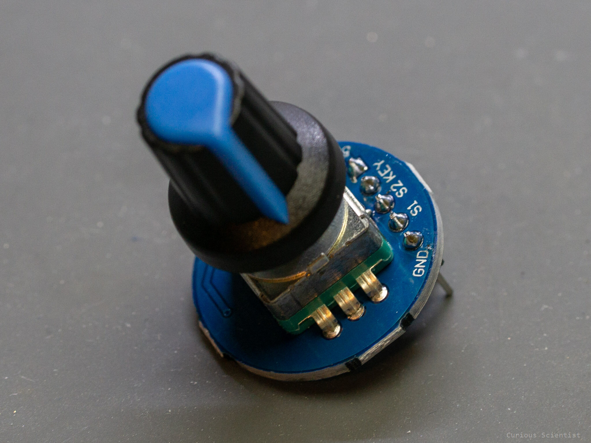
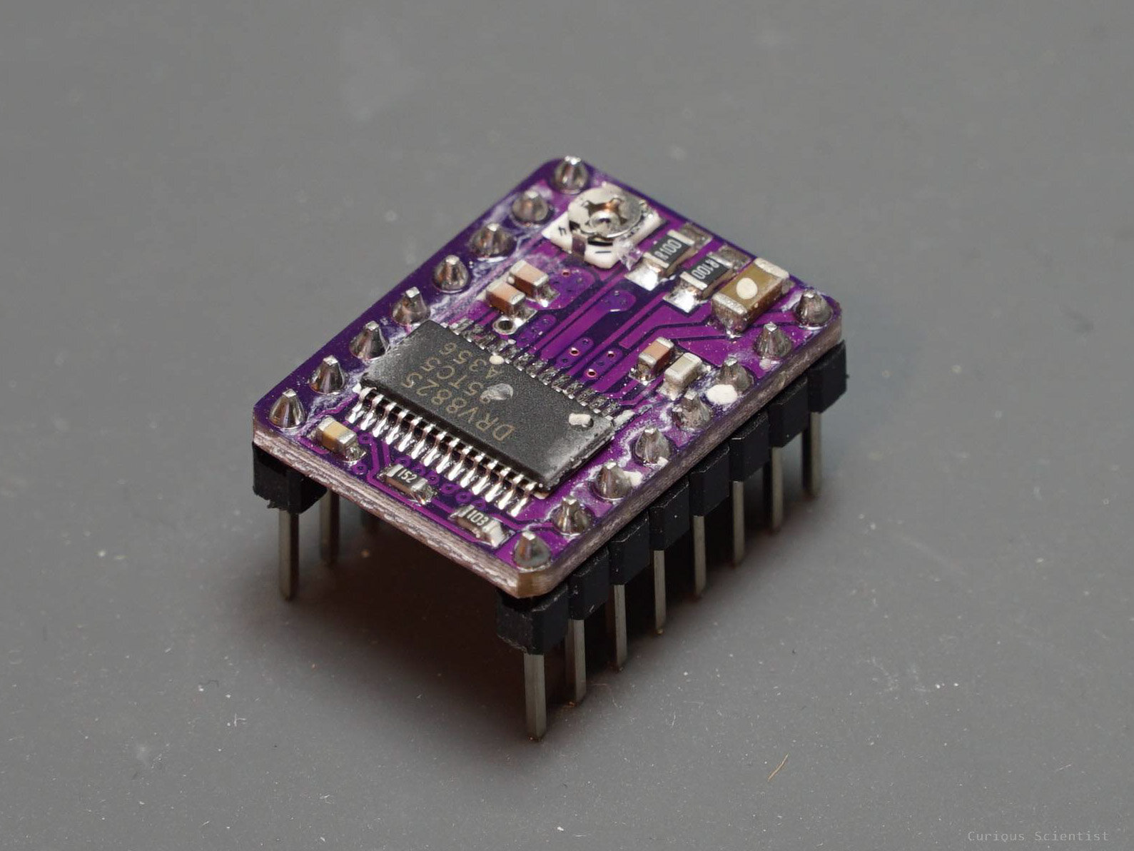
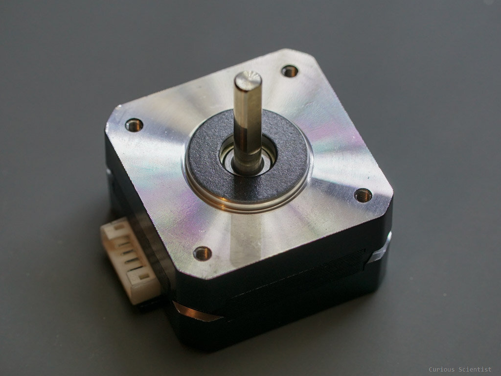
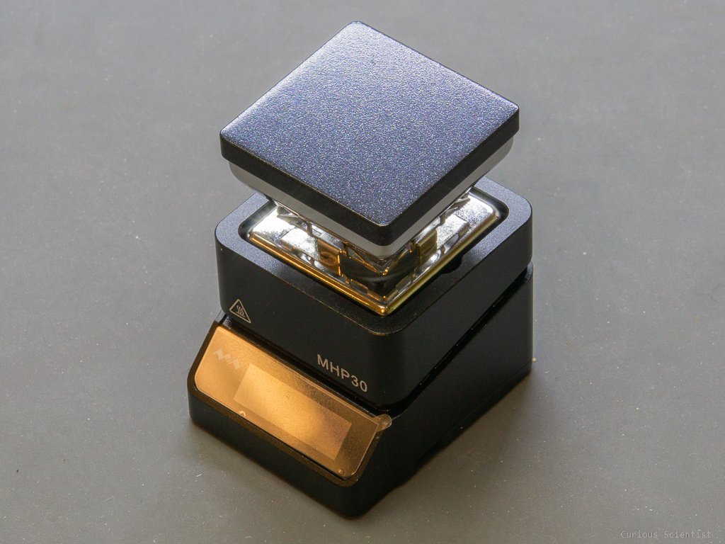
Relevant parts you might find useful
If you click on the pictures, you will be redirected to my affiliate links. If you purchase something using my links, you support my channel.
If you click on my custom PCB, you will be redirected to PCBWay’s website where you can buy my board directly.